Continental Device India Limited - datasheet pdf
Continental Device India Limited - datasheet pdf
Yes, I looked at their BC239C and thought that with a range so wide for a graded transistor, it has to be optimistic these days and the typical range is probably maintained at about 400-600. That could be OK if you bought enough and were lucky but it's been many years since I bought a 100+ of TO92 transistors that weren't all closely grouped in the middle to lower end of the range. I opt for cut tape packaging and certainly get close matching but not often where we would like it. BC549C seems to have the more credible range.
Anecdote warning: Ages ago, Graham Dicker (The designer of the ultra-simple Digi 125 amp that AKSA developed into the AKSA55) wrote a few articles for ETI magazine (yes, it originated here in Oz) and a couple were based on selecting high gain BC549C parts for use as very basic, low noise amplifiers and buffers with better performance than typical opamps. IIRC, the measured range of the Siemens parts was up to 1200 (1) and grouped around 500 which allowed a 600 min. spec to be met by about 15 parts from the hundred bought.
The labels may not have changed and the tolerances are tighter but I think the average performance of these and similar high gain transistors has gone backwards in the near 50 years they have been around .
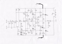
I know very well this schema ,the original creator is Bernard Corde in the 70" or 60"
the original schematic
I think the manufacturers have adopted processes that give more consistent results..................
The labels may not have changed and the tolerances are tighter but I think the average performance of these and similar high gain transistors has gone backwards in the near 50 years they have been around .
That is where the tighter tolerances come from.
And the manufacturers use those tighter tolerances to target the production towards meeting specification, rather than over-specifying to no advantage to themselves.
the same conclusion with tda1541.
first version,big production,no control ,wholesale and then after a few years, the selection came and the grades (A,R,S1,S2)appeared to end up being sold in high-end equipment but in the end, many devices of the first generation may have been sold with DAC super quality...or not
so we can have a S2 in his old plastic cd player without knowing it because the grades did not exist
You may be right there. Here's a PDF of an article on both designs I referred to - and more: http://www.aesmelbourne.org.au/wp-content/media/THE AKSA STORY.pdfI know very well this schema ,the original creator is Bernard Corde in the 70" or 60".......
Last edited:
I just put my hand on two French amp filled with very good components, I will be able to finish my nap140!!
I have not read everything about this option, do you have an opinion?
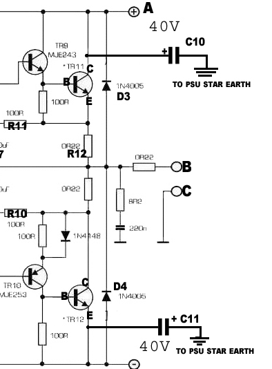
You certainly wouldn't want to put a cap from base or emitter to ground though (and that's what two of the transistors appear to have in your illustration).
Agree...those caps, if used, should connect to the negative rail.You certainly wouldn't want to put a cap from base or emitter to ground though (and that's what two of the transistors appear to have in your illustration).
BUT I wouldn't add any caps unless you are sure why you are doing it and you know your way around caps. Otherwise I'd leave it in the original Naim arrangement; Naim did not choose use bypasses for good reason.
@traderbam (you deleted your post?)
There are no emitter resistors?
As far as I can see, this is how the suggested connections go (excuse my crude drawing) - the illustration also has two extra output transistors.
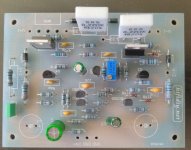
I'm fairly certain the board I have already has these caps on board.
I just checked my boards (10 years on and still incomplete!!!) and they do indeed have places for caps - just not those caps... They are caps for the driver stages (c1 and c2 in the image - not yet fitted!)
There are no emitter resistors?
As far as I can see, this is how the suggested connections go (excuse my crude drawing) - the illustration also has two extra output transistors.
I'm fairly certain the board I have already has these caps on board.
I just checked my boards (10 years on and still incomplete!!!) and they do indeed have places for caps - just not those caps... They are caps for the driver stages (c1 and c2 in the image - not yet fitted!)
Attachments
Last edited:
I believe I posted a pic of that mod. done correctly to the Nait2 here some years ago. It states bypass capacitors but I believe they are decoupling the DC supplies to the the output transistors, lowering impedance and distortion. There's no reason they won't be more effective on larger old series NAP models too as they tend to have long straight power supply leads which degrade noise performance and supply quality. You might consider whether this will be sympathetic to Naim sound quality and if you go ahead, larger caps than those suggested for the little Nait are advisable. For an amplifier built as a higher power type like NAP160, 180 or an unregulated 250, I think 1,000-1,500ufd 50V caps would be good in a mid-low ESR type like Panasonic FC.
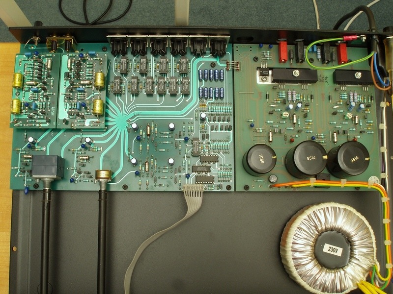
Chinese NAP140 clone boards actually follow the NAP250 schematic and suggest supply voltages which are for a regulated supply amplifier running off +/- 40V rails. The NAP 140 could use the same PCB with appropriate lower, unregulated +/- 34V supply voltages, a few changes to the small transistor types, and the RC networks in the driver transistor bases. It seems though, most builders just follow the kit suggestions with the wrong schematic, and wind with a odd mix of substitute parts in a NAP250 design that really doesn't sound much good.
When you replace the VAS transistors with original ZTX653/753 types and carefully select substitutes for the obsolete small signal types, things begin get better. or closer to the Naim sound. So what about Naim sound? Well I guess you make your choice and build what you like even if its not like anything original. We do like to tinker and experiment to see what sound effects we can make by fitting wrong parts anyway - I guess its all fun if nobody gets hurt and no damage is done")
Chinese NAP140 clone boards actually follow the NAP250 schematic and suggest supply voltages which are for a regulated supply amplifier running off +/- 40V rails. The NAP 140 could use the same PCB with appropriate lower, unregulated +/- 34V supply voltages, a few changes to the small transistor types, and the RC networks in the driver transistor bases. It seems though, most builders just follow the kit suggestions with the wrong schematic, and wind with a odd mix of substitute parts in a NAP250 design that really doesn't sound much good.
When you replace the VAS transistors with original ZTX653/753 types and carefully select substitutes for the obsolete small signal types, things begin get better. or closer to the Naim sound. So what about Naim sound? Well I guess you make your choice and build what you like even if its not like anything original. We do like to tinker and experiment to see what sound effects we can make by fitting wrong parts anyway - I guess its all fun if nobody gets hurt and no damage is done
You certainly wouldn't want to put a cap from base or emitter to ground though (and that's what two of the transistors appear to have in your illustration).
I've been looking at that decoupling mod for the Nap140 too and have gotten me some low ESR Panasonics rated to 50v to test.
Is C11 a bad idea?
(The schematic is from the Acoustica mod list).
Attachments
That's interesting - something I've considered myself for a small amplifier but I've been too lazy to lay out a PCB that would fit an appropriate case. There is a hand drawn schematic with the appropriate components for the complete Nait on the web if you Google it. That gives you the original NAP90 power amplifier schematic, suitable parts and grades too if you check the NAP 90 pics there, as I imagine you already have.
Comments about the transistor types still apply though and a high gain, mismatched long tailed pair is a trick h[/I] to get the DC offset acceptable.
Comments about the transistor types still apply though and a high gain, mismatched long tailed pair is a trick h[/I] to get the DC offset acceptable.
the nap 90 is the same to nait 2,3 and probably the 5
An externally hosted image should be here but it was not working when we last tested it.
- Home
- Amplifiers
- Solid State
- NAP-140 Clone Amp Kit on eBay