Member
Joined 2009
Paid Member
The chassis must be connected to safety earth in your house. If you get a shock from that, you have a serious issue and you should have an electrician fix it. If the chassis was floating, best not do that, connect it to mains safety earth. For DIY, use a 3-wire mains cable, don't try to make a double-insulated 2-core product.
Connect 1R resistor1/4W in series with 100nf parallel to output .
Hot resistor means oscillation.
I haven't got the 1R resistor1/4W and 100nf capacitor yet. I managed to swap out the genuine 2SC2922 with the fake ones and the bulb dimmed down as it should.
If it was really oscillation, why would genuine 2922 cause oscillation?
Wanted to edit the original post but I exceeded the time limit.
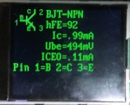
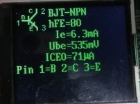
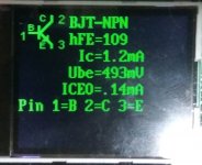
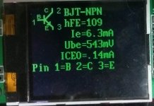
I got myself one of those cheap transistor tester from fleabay and here are the results.
The first two (92hFE, 80hFE) are fakes and the last two (109hFE, 109hFE) are genuine ones.
I got myself one of those cheap transistor tester from fleabay and here are the results.
The first two (92hFE, 80hFE) are fakes and the last two (109hFE, 109hFE) are genuine ones.
Attachments
I haven't got the 1R resistor1/4W and 100nf capacitor yet. I managed to swap out the genuine 2SC2922 with the fake ones and the bulb dimmed down as it should.
If it was really oscillation, why would genuine 2922 cause oscillation?
The genuine 2922 probably has higher HF gain, and hence would be more likely to oscillate.
The genuine 2922 probably has higher HF gain, and hence would be more likely to oscillate.
Any suggestions on how I can reduce the gain? Increase certain resistors to reduce the gain?
Forget the idea of changing the amplifier design to get around the problem. The design works well and so does the PCB. If there is a problem, it will be in the construction. Recheck your passive parts for resistor colour codes and transistor orientation etc. Not all components supplied may have the correct pinout and kits may have substitute parts that require reversal or even another pin arrangement. For example, note that the Vbe multiplier transistors are fitted from the bottom side. If you fit the same type from from the top side, E and C will be reversed.
You will probably experience instabity of bias until the board is assembled properly into the case and allowed to warm up and stabilize with the cover on - that's how the amplifiers are designed to work, with thermal sensing from being close to the aluminium case bottom plate. There are no clear assembly instructions that I have seen on the web and this is not a typical simple assembly. The power transistors should be mounted on a thick heat spreader that fits the long central slot in the PCB, before being adjusted for height, bolted down and soldered. You can see this in pics of the real thing already posted here.
BTW, measuring transistors with Atmega 328 testers is a waste of time - they give results that are bunched together and all the same in each bunch or occasionally give random high/low values. They may be useful as go/no go testers but that's about all. Look at your measurements - see how they are closely grouped? Those are very unlikely results for any sample of 4 transistors.
I suggest that power transistor gain or Hfe, should be tested at much higher current, like perhaps 0.5A and on a heatsink, if you want meaningful results. Gain measurements that are in the milliamp region are pointless on anything but small signal types (TO92 size etc.) which work at that sort of current. There are meters for this that aren't terribly expensive but certainly cost more than $10 and require a plugpack power supply too.
Dy294 Digital Transistor Tester Reviews - Online Shopping Dy294 Digital Transistor Tester Reviews on Aliexpress.com | Alibaba Group
dy294 digital transistor tester
Member
Joined 2009
Paid Member
I think I'm ready to throw in the towel on this one. With the fake 2922 even though the bulb limiter is dim the bias at R12 is 14mV with the trimmer all the way down.
I think the NAP200 is too big for me.
Penmarker - we don't throw in towels around here !!! pull yourself together, you are doing well and perfectly capable of taming this amp!

Get yourself a nice Teh Tarik and recover your energy
")
Back in July, you had friends over to listen to the amp and you all enjoyed it. The proof of success is already there ! - now we're just foolin' around a bit.
A bit of dc on the output is nothing to worry about providing it's not too high. I wouldn't worry about anything less than 50mV, especially on an amplifier that has a bit of thermal drift built into the design like this one. There's no sudden point where it's a problem, 55mV is fine too. Instead of making this a big headache, forget perfection, get the amp back into a solid working condition, in the box and enjoy it. There are other things you can build and enjoy and learn from. If you really get frustrated about the drift I have a version of this amp in which I engineered a different approach to thermal stability and I'll send you a pair of boards should you need. Make sure to stay safe, earth that chassis - you have British wall sockets for the mains supply in your country, with big chunky brass earth pins on the plugs so there are no excuses for saving your family from the grief of your electrocution !
Work on one channel at a time, not both together. Focus on one board first. Get a clean space to work on it and take your time, working methodically. Try not to have too many things going on at once, change one thing at a time. Verify your work as you go. If you have some parts you don't trust then best replace them rather than have doubts. What are you missing ?
Last edited:
I can't thank you everyone here enough, especially you two Ian and Bigun!
Seeing how I have all measurements within ballpark with Algar's made me think again. Something must be off by a tiny bit. And then Ian's comment hinted the VBE multiplier transistors could be affected by temperature and I checked. Sure enough it was fitted backwards. Both of them.
So I've flipped and everything seems normal. All measurements are good, speaker out only has 12mV and 10mV offset. R12 biasing stabilized after some 10 odd minutes.
What's left is just to hook them up and hang tight.
Attachments
Thank you very much traderbam, now listening to some spotify in the meantime. I'll put on some CDs or records later when its a little earlier during the day (its 12.11am now). I got the case from taobao through an agent. If you can overlook the inaccurate machining making it hard to put together if the side walls are screwed tightly, its a nice little chassis.Nice case. Good luck with the audition.
Would you mind posting the schematic of you circuit?
Please check the following post for schematic.:
If you click to the source of the post you'll see a few posts up the BOM as well.And latest schematic with parts ID, notes and volt readings...
This has been a tremendous source of reference seeing how there aren't any specific NAP200 schematics around, only generic NAP series schematics.
Thanks Penmaker. There are some things in that schematic that don't make sense to me. I seem to think you have a real NAP200...is that right? If so, would you be able to take some close-up photos of the amplifier section of the circuit board...so I can make out resistor colours and capacitor orientations?
Member
Joined 2009
Paid Member
Mine is the generic clone board. I bought it some time last year as an assembled board and has replaced everything in it except for the power reservoir caps and the resistors.Thanks Penmaker. There are some things in that schematic that don't make sense to me. I seem to think you have a real NAP200...is that right? If so, would you be able to take some close-up photos of the amplifier section of the circuit board...so I can make out resistor colours and capacitor orientations?
I took some photos previously, some of the resistor colors are visible but I think others are a bit blurry. You'll be able to make out the silkscreen tant orientations, but not the components since the labels are facing away from the camera in most of the shots.
NAP200 clone - Google Drive
I've been reading through the thread and there has been numerous warnings against that.Could be handy to have some ventilation in that case.
For maybe other builds I'd say that would be a great feature on the case.
Member
Joined 2009
Paid Member
Mine is the generic clone board. I bought it some time last year as an assembled board and has replaced everything in it except for the power reservoir caps and the resistors.
I took some photos previously, some of the resistor colors are visible but I think others are a bit blurry. You'll be able to make out the silkscreen tant orientations, but not the components since the labels are facing away from the camera in most of the shots.
NAP200 clone - Google Drive
I've been reading through the thread and there has been numerous warnings against that.
For maybe other builds I'd say that would be a great feature on the case.
That looks very nice Penmarker - good work!
Is that solid copper wire you are using to connect the speaker and RCA sockets?
It looks like it's insulated but I can't really see for sure.
But do consider supporting it somehow, as over time it may sag with the heat inside the chassis and cause issues.
That looks very nice Penmarker - good work!
Is that solid copper wire you are using to connect the speaker and RCA sockets?
It looks like it's insulated but I can't really see for sure.
But do consider supporting it somehow, as over time it may sag with the heat inside the chassis and cause issues.
Thanks a lot Tony! That does look better than it looks now
 Currently the board looks a little dirtier with some flux residue, some tiny burnt marks, etc because I've been flipping it over back and forth for reworking.
The copper was actually magnet wire with thin enamel insulation. I bought it originally thinking it was solid core copper wire with teflon insulation. It is very stiff and thick, hard to work with.
I've removed them and replaced the speaker connection and RCA input with 16AWG and 30AWG hook up wires.
The speaker wires are quite stiff so I used some hot snot to keep them from damaging the solder traces.
I don't dare share more recent pictures, the amp looks uglier on the inside.
I notice you haven't fitted a heat spreader bar between the output transistors and the case, as discussed at the beginning of the NAP200 posts in this thread. Sure, we see other build pics of the kits without one too, since it makes construction easier and cheaper. The amplifier will probably work OK without one at modest power but don't try to push the amplifier anywhere near the original design's maximum (200W/4R) power rating. You might be in for a nasty surprise and sooner than you think, in hot weather.
I haven't been pushing them at all with my pre volume knob at around 9-10 o'clock. The top of the case gets slightly warm and the bottom feels warmer by a bit after a few hours listening.I notice you haven't fitted a heat spreader bar between the output transistors and the case, as discussed at the beginning of the NAP200 posts in this thread. Sure, we see other build pics of the kits without one too, since it makes construction easier and cheaper. The amplifier will probably work OK without one at modest power but don't try to push the amplifier anywhere near the original design's maximum (200W/4R) power rating. You might be in for a nasty surprise and sooner than you think, in hot weather.
I've been trying to source some heat spreaders around here but aluminum shops don't take small orders. Some hardware stores do carry aluminum profiles and bits n pieces but none are the correct shape.
I'm sorry for double posting. Just want to ask a quick question regarding the heat situation.
Currently my kit is using 8mm standoffs. I've found an aluminum spreader on taobao but instead of 8-9mm thickness which is suitable for my standoff height, it is 13.6mm
厂家现货 专业型材 250毫米长度 13.6X62规格金封管导热桥-淘宝网全球站
If I get 12mm standoffs so I can use that heat spreader, will there be any adverse effects with regards to the air movement due to convection and what not?
4mm doesn't look a lot here looking at my caliper, but I don't know how much that affects the flow of air in the case.
- Home
- Amplifiers
- Solid State
- NAP-140 Clone Amp Kit on eBay