Minimise the temperature differentials.Any way to decrease the DC by default?
Use more different HFE input transitors?
Changing resistors?
On the point of testing everything thoroughly, if anyone bothers to read back to look at just a few builds in this thread for themselves, most problems earlier, were found to be with assembly errors. Apart from confused colour codes of resistors, the biggest problem was understanding that TO92 transistor pinouts are not standard and when substitutes or fakes are supplied in kits, errors occur. For example, the original ZTX653/753 VAS transitors have a different pinout to common substitutes 2SD667/B647. Some PCBs were modified to suit the subs and marked appropriately but many were not and kit sellers did not provide advice to this effect. The same problem occurred when 2SC, 2SA small signal transistor types were substituted for BC550, BC384 and 2N types. Chaos ensued rather than a bit of caution, common sense and looking up datasheets.
Certainly, if you have rail voltage at the output, you either have a shorted output transistor, shorted connections or wrong transistor types fitted to the board you are using. Did you also check for solder splashes and the isolation between transistor collectors and the heatsink? Remember, not all boards are the same and there are dozens of different clones out there. So check it twice, 3 times or more by testing transistors to ensure that all component leads are correctly identified and fitted - it only takes one blunder to ruin the whole project
Certainly, if you have rail voltage at the output, you either have a shorted output transistor, shorted connections or wrong transistor types fitted to the board you are using. Did you also check for solder splashes and the isolation between transistor collectors and the heatsink? Remember, not all boards are the same and there are dozens of different clones out there. So check it twice, 3 times or more by testing transistors to ensure that all component leads are correctly identified and fitted - it only takes one blunder to ruin the whole project
Ok, but what controls the base DC out?
How can I reduce that?
In circuits using feedback loop practically anything can be a factor for DC drift. In your particular case with some thermal instability you can maybe read a little bit about Vbe multipliers and how to match them thermally to your output transistors. There is a lot of information on the internet. Or check D. Self book on power amplifiers.
Also consider the possibility of mild oscillation. You need an oscilloscope to troubleshoot...
If the DC offset is stable and close to zero, it can be affected by the balance of the resistor values in the input and the feedback (the LTP bases). I wrote about that several times on this thread. Won't do it again.
I wrote about that several times on this thread. Won't do it again.
It is also an information whos posts I should read to find info.
")
Have you boxed up the unit when you're measuring the output DC? Are the transistors matched?I recently bought a zerozone nap140 pcb and I have a question about DC drift at the output.
I used bd139/140 instead of ZTX, bc546b for input, bd139/140 for driver and 2n3055 for power transistor. Protection part left out.
Fired up with 2x30VDC, input shorted, 8 ohm resistor load. Measeured the 0.22R resistor and set the bias to be 3mV, so around 14mA.
The problem is the output DC. It starts at around 6-8mV, and slowly (1 min) goes up to 15mV. As soon as I touch the VAS bd140, the voltage drops to 12mV (in 1 second). Strangely if I touch the VAS bd139, nothing happens. If I also touch the input transistors top, it drops more back to around 10mV. They don't seem hot, but then why would they drop? Is there a way to decrease the DC and also reduce the heat drift?
Does it drifts so much for others also? I'm afraid if I put it in a box the heat may go up and the drift increases lot more.
Did anybody compare the clone with the original? There is also NP200 clone out there, do you know which one is close to the original Naim sound? I have never owned Naim products and was never interested in them until I have heard their integrated amps. They play very balanced. The tonality and rhythm are very good. I always read on the forums the PRAT thing with Naim and I guess that's what they meant. I am impressed although I can understand it is not being everyone's cup of tea.
There is little point in matching the transistors in a Naim Clone. They all operate at different voltages and different currents.
There's quite an extensive area in the Naim factory for tolerance grading & matching for both semi & passive components.
They use very accurate bench measurement machinery for this purpose as they maintain it holds the brand sound across the ranges and down the production lines.
So we have seen in their promo videos over the years but there's no hint of which components are tested, how many and whether that refers to routine incoming sample quality checks or 100% matching of a few specific components. Nothing informative is really being said or demonstrated and I think the info Naim reveals is generalised and evasive - like that of any manufacturer who is vitally concerned for their process security when promoting their image as a high-end manufacturer.There's quite an extensive area in the Naim factory for tolerance grading & matching for both semi & passive components......
Obviously, some degree of testing and matching is occurring but with modern, automated 'pick and place' or through-hole assembly, the avenues for individually matched parts are quite limited and would now mean a lot of expensive hand SMD work - rather nullifying the benefits of the modern assembly plant now in use.
So we have seen in their promo videos over the years but there's no hint of which components are tested, how many and whether that refers to routine incoming sample quality checks or 100% matching of a few specific components. Nothing informative is really being said or demonstrated and I think the info Naim reveals is generalised and evasive - like that of any manufacturer who is vitally concerned for their process security when promoting their image as a high-end manufacturer.
Obviously, some degree of testing and matching is occurring but with modern, automated 'pick and place' or through-hole assembly, the avenues for individually matched parts are quite limited and would now mean a lot of expensive hand SMD work - rather nullifying the benefits of the modern assembly plant now in use.
I can verify this, having been there on the AES technical visit in 2008 where the testing/selection processes were discussed at length.
Hth.
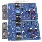
Double check these four transistors circled in the attached photo. Compare your new units with the supplied units whether their pins are 123 or 321.
Mine behaved this way when I got replacement transistors because of regional difference.
Double check every one of the other transistors as well.
Use mains bulb tester.
Attachments
I'm revisiting this amp because of the transformer mishap last time. I've gotten extra transistors and a transistor tester to measure and match the HFEs.I wrote that years ago in this thread, but it's obviously hard to read through it. It's very big now, so I'll repeat it for all people building this kit:
You should never power up this board with the power transistors!
First power-up should be with the drivers only. The circuit works fine on drivers only and output floating (no load)
That has several benefits:
1. If something burns, it will be cheap.
2. If nothing burns, but still the circuit is not working, you'll have generally more time to troubleshoot and measure before it fails permanently... In the worst case, something cheap will overheat and burn.
3. You can verify the whole circuit works - check output offset, check bias spreader work by turning the trimmer and measuring the voltage change between the driver transistors bases.
4. Leave the bias at something like 2V between base-to-base of the drivers. Then, add the power transistors and turn the trimmer up (by now you'll now what is the up direction) until current flows in the output resistors (5-7mV across). That's it!
Play some music.
I kept the 2922 off for now and powered the board through a limiter bulb.
I cannot seem to adjust the bias at the R12 and it stays between 1.2-1.6mV. Both channels are exhibiting the same symptom.
Another is the voltage on TR9 base is measured as 0.5V by Algar however mine is 1.2V. Most of the other measurements are within the ballpark though. I might have missed some measurements, it's pretty late already here now.
** Edit
D'oh! Sorry it's late and I need some sleep. I'm gonna need to put the 2922 before adjusting the bias. In the meantime I'll measure other parameters.
Last edited:
Last night I fired the amp up with the 2922 in place. With the limiter bulb in place the bulb lit up pretty bright. I measured the voltage in the rails and they were around 3.9V and -3.9V.
It measured ok before the transistors were in, I checked all the wiring but everything seems fine.
It measured ok before the transistors were in, I checked all the wiring but everything seems fine.
Last night I fired the amp up with the 2922 in place. With the limiter bulb in place the bulb lit up pretty bright. I measured the voltage in the rails and they were around 3.9V and -3.9V.
It measured ok before the transistors were in, I checked all the wiring but everything seems fine.
Connect 1R resistor1/4W in series with 100nf parallel to output .
Hot resistor means oscillation.
Connect 1R resistor1/4W in series with 100nf parallel to output .
Hot resistor means oscillation.
Thank you very much.
It could also be something else entirely....
Today at lunchtime I went home from office to conduct some more tests when I accidentally touched the chassis. It was live and i got shocked. I unhooked the board from the transformer and turned it on again and there's no shock. Tested the transformer outputs unloaded and they're around 31V to center tap.
Because of time constraints I can't test further. Eveballing the board to see if there's any dangling bits of component leg or solder touching the chassis below and nothing looks like they're poking out further than they should.
I feel like I'm the opposite of having Midas touch.
- Home
- Amplifiers
- Solid State
- NAP-140 Clone Amp Kit on eBay