LOOP AREA !
where are the signal pairs?
Agree........

for signal please use thin wire and twisted if you prefer unshielded...
Nope, no diagrams sir. Bought the board assembled and tested.Yes, the thump is present. Do you received a schematic or some diagram and component values from Chinese people ?
Sent from my Nexus 5 using Tapatalk
Ah, I learn new things every dayAgree........
for signal please use thin wire and twisted if you prefer unshielded...
 I do have some microphone cables left from a previous project.
But other than that, anything wrong with my build?
I'm still waiting for a power switch to mount at the front. Guess fleaBay is taking their sweet time.
The Earth wire is permanently fixed to the chassis with a screw and the surface is scraped off any coating or paint to ensure conductivity.
There are no exposed conductive parts except for the ones that need to be exposed which are the connectors.
I've measured the DCV offset and both channels are between 21-22mV. Ideally it should be lower than 15mV correct?
There are no exposed conductive parts except for the ones that need to be exposed which are the connectors.
I've measured the DCV offset and both channels are between 21-22mV. Ideally it should be lower than 15mV correct?
What about those sockets without protective earth ? In my apartment I have protective earth only in bathroom and kitchen.Is the Protective Earth wire permanently and mechanically fixed to the Chassis/enclosure?
Are there any exposed conductive parts?
These should be connected to the protected Chassis.
Sent from my Nexus 5 using Tapatalk
Dangerously.I don't know how you can build a ClassII product without the PE wire connected.
"Ideally" is just that - an Ideal number that will seldom have any significance below an arbitrary 50mV. This amount of offset is usually considered to be a hint of problems developing in commercial amplifiers but some leave the factory with even up to 70mV offset and more...I've measured the DCV offset and both channels are between 21-22mV. Ideally it should be lower than 15mV correct?
I feel sorry for OCD sufferers who believe they must achieve 0.0 mV for some reason. Don't tell them it's going to change during use and drift over time anyway. There, something else to obsess over now

"Ideally" is just that - an Ideal number that will seldom have any significance below an arbitrary 50mV. This amount of offset is usually considered to be a hint of problems developing in commercial amplifiers but some leave the factory with even up to 70mV offset and more.
I feel sorry for OCD sufferers who believe they must achieve 0.0 mV for some reason. Don't tell them it's going to change during use and drift over time anyway. There, something else to obsess over now
I've been following an Audiokarma thread regarding DC offset and read through some good measurements. This is my first build and I didn't handpick any components so I'm not too anal about the measurements
it does sing and it sings well. These satellite speakers remind me of the small but capable HiVi Swans A30 desktop speakers. Of course its a pair of cheapo satellites so I don't expect much!Now, next is getting a pair of decent speakers...
Nice to know my numbers line up somewhat with member EchoWars. The interesting point that has been made many times in this long thread, is that whilst DC offset is certainly controlled in Naim amps, the main game is about ensuring the right amount of imbalance of the log-tailed pair transistors, the LTP. This deliberately limits cancellation of 2nd harmonic distortion, as would occur in a precisely matched pair of transistors with balanced bias currents. It also means using similar parts there to the original spec.
Attempts to change this design feature usually result in pretty mediodre sound quality as discussed here recently, hence the advice; build it as an original Naim or build something else.
Attempts to change this design feature usually result in pretty mediodre sound quality as discussed here recently, hence the advice; build it as an original Naim or build something else.
Thanks a lot Ian for that explanation. I've read through most of the thread, though I did skip through some of the more technical explanations due to having no electrical/electronics knowledge.
Now I'm in the process of selling my powered monitors and getting a pair of passive speakers for the amp.
Now I'm in the process of selling my powered monitors and getting a pair of passive speakers for the amp.
Naim 140 ebay project. Not yet!
Dear group, I don't know that you remember me but this was my first audio self build. I have put this aside due to frustration. That said I did finally arrived at a working amplifier before putting it away, what I have accomplished in large part what I have learned in here and trial in error,LOL.( DONT DO THAT! )
My Problem!!! I have a low frequency hummm, a pronounced low-frequency hmmm but not the total silence I'm trying to achieve. The only thing that I have to chassis ground is the 120 V line in to my transformer. Am I missing something that is obvious to those of you that have built this? I guess what I'm asking is should this DC voltage be chassis grounded and if so where and what?
Attachments
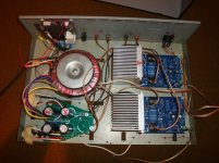
Your wiring may only be temporary, but you will certainly increase hum with all those long, loopy connecting wires. Have a look at how Naim do it, for starters. Next, your signal wiring is plain twinflex when it should be shielded or at least closely twisted pairs, routed away from noisy power wiring.
Where is your signal input ground connected?
Where is your signal input ground connected?
Ian, I will redo the input wiring for starters. Should I eliminate all of this speaker wire from the internal chassis? You're right this is not a finished product this was just trying to get something functional which I did accomplish. That said do you think any of this DC circuitry should be chassis grounded. Thanks
Last edited:
Input ground method
The input signal is grounded only to the amplifier boards themselves the positive and negative RCA inputs go directly into the amplifier boards
Your wiring may only be temporary, but you will certainly increase hum with all those long, loopy connecting wires. Have a look at how Naim do it, for starters. Next, your signal wiring is plain twinflex when it should be shielded or at least closely twisted pairs, routed away from noisy power wiring.
Where is your signal input ground connected?
The input signal is grounded only to the amplifier boards themselves the positive and negative RCA inputs go directly into the amplifier boards
An overall principle of protective earth wired power supplies, like all DIYs should be doing in countries where it is possible or mandated, is to earth the amplifier once and once only to the chassis. Here's the general plan with details, suiting almost all amplifiers: Earthing (Grounding) Your Hi-Fi - Tricks and Techniques
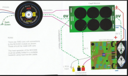
Naim NAP amplifiers were originally developed back in the 1970s and wiring schemes have improved somewhat since they were introduced. The old models like NAP140 had few revisions over the years they were produced, until more recent models displaced them. Hence you see some anachronistic wiring schemes on them like the plain wiring still cable tied or loomed in bundles. It looks professional and "old school" and but is usually technically inferior to properly twisted power supply pairs or triples for balanced supplies, twisted pair output leads and twisted or shielded wire signal wiring.
Good Naim clone board wiring is shown here in this thread a few times but you can still follow the connections using the better technique anyway. Here's a diagram showing how a up-market Naim Clone is wired.
Attachments
Your wiring may only be temporary, but you will certainly increase hum with all those long, loopy connecting wires. Have a look at how Naim do it, for starters. Next, your signal wiring is plain twinflex when it should be shielded or at least closely twisted pairs, routed away from noisy power wiring.
Where is your signal input ground connected?
? Ian would you consider silicone rubber insulated wiring a good choice for the internal wiring? Thanks again
- Home
- Amplifiers
- Solid State
- NAP-140 Clone Amp Kit on eBay