Ok after very fine tuning here and there I have the final noise level that I'm comfortable with, and AndrewT may be more happy ")
I have now 0.1mVac (89db down from 1W) at the output, and I cannot here a thing in the speakers.
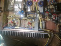
A few things that I did: Grounded the LTP aluminum block, correctly installed the polysterene caps to insure that the outer foil is the one close to gnd (biggest improvement), fine tuning of the transformer rotation for lowest noise.
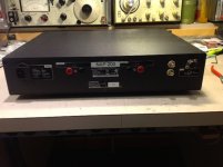
Here the last version of the rear panel, I added an extra RCA input.
BTW my ALW Jung regs has 0.07mv ripple of the preamp 24V, pretty good for an input of 80mVac ripple.
I have now 0.1mVac (89db down from 1W) at the output, and I cannot here a thing in the speakers.
A few things that I did: Grounded the LTP aluminum block, correctly installed the polysterene caps to insure that the outer foil is the one close to gnd (biggest improvement), fine tuning of the transformer rotation for lowest noise.
Here the last version of the rear panel, I added an extra RCA input.
BTW my ALW Jung regs has 0.07mv ripple of the preamp 24V, pretty good for an input of 80mVac ripple.
Attachments
Last edited:

I don't know whether anyone is still building the NAP200 clone, but if stuck for which pre-amp to use then the LDR attenuator described here works extremely well with this amp:
http://www.diyaudio.com/forums/anal...d-ldr-volume-source-selection-controller.html
Chris
http://www.diyaudio.com/forums/anal...d-ldr-volume-source-selection-controller.html
Chris
Are ppl here still interested in NAP140 original design and AB comparison ?
I am wondering how many are still using this amplifier ?
I have finished soldering 4 identical boards that corresponds to NAP 140 original design, leaving headroom for front-end supply and other modifications/snake-oils on the PCB-s.
As i have written before in this thread, there are 4 transformers sitting and doin nothing.
I could make 2 identical PSU-s from 4 transformers with the 48-50VDC/~300-400W per PSU and connect all four boards to these PSU's for the final two stereo AB solution and test everything(grounding, cabling, EMI filters, Snakes and oils, film bypass trends and so on).
It took long, as everything i have gotten so far is free or very cheap, so, it can be partially wasted.
I would allready have done it if only the transformers were lower voltage, about 40VDC, so with the 50VDC is this worth the hassle, cuz most of us here don't have that kind of crazy voltage on they AMP boards(??
Also what bug's me is the metal case... because amplifiers sound different vs open environment, usually better @ last one.
EDIT:
As i have listened to few of the APEX amplifiers, i still like the naim clone(H-140 modified) the most... still more controlled in base region, sound is kinda exploding from speakers, i like that.
I am wondering how many are still using this amplifier ?
I have finished soldering 4 identical boards that corresponds to NAP 140 original design, leaving headroom for front-end supply and other modifications/snake-oils on the PCB-s.
As i have written before in this thread, there are 4 transformers sitting and doin nothing.
I could make 2 identical PSU-s from 4 transformers with the 48-50VDC/~300-400W per PSU and connect all four boards to these PSU's for the final two stereo AB solution and test everything(grounding, cabling, EMI filters, Snakes and oils, film bypass trends and so on).
It took long, as everything i have gotten so far is free or very cheap, so, it can be partially wasted.
I would allready have done it if only the transformers were lower voltage, about 40VDC, so with the 50VDC is this worth the hassle, cuz most of us here don't have that kind of crazy voltage on they AMP boards
(??Also what bug's me is the metal case... because amplifiers sound different vs open environment, usually better @ last one.
EDIT:
As i have listened to few of the APEX amplifiers, i still like the naim clone(H-140 modified) the most... still more controlled in base region, sound is kinda exploding from speakers, i like that.
Last edited:
Any tip how to determine the outer foil of polystyrene caps ?
Sent from my Nexus 5 using Tapatalk
If you have a scope then set it so that touching the probe tip (ground lead floating) gives you a screenfull (or as close as like) of noise / 50Hz junk.
Connect probe to cap. Probe tip to one leg, ground lead to other leg. Grasp cap between fingers. Reverse leads of scope probe to cap and test again.
The largest amount of junk is with the probe tip connected to the outer (screen) of the cap. That's the side that should go nearest ground in your application.
Are ppl here still interested in NAP140 original design and AB comparison ?
I am wondering how many are still using this amplifier ?
I'm still interested in developing mine further, though I haven't had much time to do so of late.
I was very impressed after the initial build up and still am. That probably just means the rest of the system is weak though honestly I think it sounds fine. Mine has been switched on pretty much continuously for the last 8 or 9 months.I have another set of boards to build up but need a decent transformer.
Then I think I would go to an active x-over as the best option.
I can't count the number of times this subject of higher voltage supply rails is raised and I know you would have read some replies already......I would allready have done it if only the transformers were lower voltage, about 40VDC, so with the 50VDC is this worth the hassle, cuz most of us here don't have that kind of crazy voltage on they AMP boards.....
Let's go over the main issues:
1. The components specified are all low voltage parts so to simply use higher voltage supplies, you need to substitute higher voltage rated transistors or cascode the originals with more to allow higher supply voltages to be used within the original design's power limitation.
2. Sound quality is heavily dependent on the present transistor lineup used in the VAS and the input stage design too, so simple substitution (which I've tried myself on several occasions) is interesting in the effects but just isn't right and usually becomes annoying to listen to over time. Different transistors, as you find in kits, are often the reason people don't especially like the clone sound.
3.Miller frequency compensation is affected by parts changes too and contrary to best practice, large Cob instead of small is specified here, relative to the Miller Cap. size. This has a profound affect on stability and sound quality, because one part of the capacitance is fixed and the other (Cob) is gyrating much more than is ideal, with the signal voltage.
4. You could, as nigel pearson posted a design idea here for the purpose some years ago, supply the output transitors with say, +/- 50V and reduce it to 40V for the front end with simple discrete regulators. I have not attempted it but previous efforts with some good sounding amplifiers were not great. The amp had lost some harmonic character and there are arguments against regulation, regarding speaker interaction but I've not investigated to be so certain myself.
Generally, a lot of guys are using 30VAC transformers with their clones and having little trouble since they are supplied with different and usually higher rated parts. The results are OK for them, so let them enjoy but if you want something close to Naim sound, you should follow their formula which scarcely changed for some models, right up to recent years.
Why not use your transformers with different design amplifiers that can take the higher voltage, for your active-X over system. I doubt very much that true Naim design amps will translate to an active system anyway, so why not build standard designs Like one of ljm's L series kits that handle higher voltages - no problem
.
Last edited:
I wonder if it's about time to organise a group buy for some Naim style clone transformers. You know the sort, 2 x V-0-V with dual and tappable primaries, maybe even mildly tappable secondaries and enough VA for a decent job.
I wonder what the per unit price would be for a 100 off run?
Any thoughts?
I wonder what the per unit price would be for a 100 off run?
Any thoughts?
Multi tapping a toroid is very expensive and difficult - a 2 X 28VAC transformer in a standard rating like 160 or 300VA would be a reasonable group buy project but they would not be viable outside you own region - freight of heavy items is the largest cost for international trade.
If you are building NAP 140 clones, 160VA is all you really need - 2 x 160VA would make a great dual mono supply. One would be just enough for full peak power into 8R - more than enough for most homes anyway.
If you are building NAP 140 clones, 160VA is all you really need - 2 x 160VA would make a great dual mono supply. One would be just enough for full peak power into 8R - more than enough for most homes anyway.
Ian Finch, that is what i was afraid of, as the higher voltage will affect sound.
It would only make sense to everybody, if i would test different amplifiers on the 50V rails. Other amplifiers do not interest me right now as it eats lots of time and money.
I agree, different components is what makes naim clones sound not good.
There is also resistor values, especially those which are connected from VAS to Drivers base... all of those vary depending on the rail voltage, transformer size and the last is transistor parameters i believe, maybe even ground and rail wiring.
For example, take a NAP110, 135, 140, 160, 250... all five have different values between drivers and VAS.
That's correct, the variations are there to preserve the bias currents in the input & VAS but the RC network in the driver bases is another matter that was explained (and guessed about a lot) here and at the headquarters of Naim hacking, PFM forum.
The NAP140 clone circuit you see on the web so often is not the 140. It's actually one of the bridged amplifier boards used in the NAP250 which were also used in the bridged NAP135 monobloc amps. Theirs is the only recognized schematic drawing that has become available and clone makers named it NAP140 because it suited their sales pitch, evoking a model with a reputation as the best sounding. So its identity has become confused by false information - not that there is much effective difference anyway, because 40V suits the NAP250/135 design. Original NAP140 had only 34V rails and minor changes to the front end biasing resistors too.
You are aware the XTX653/753 are Vceo 100V max. With line variation taken into account, you are unsafe in the VAS, you will also need a higher Vceo input pair, drivers are OK if using MJE243/253 and output transistors probably fine too. You still need to recalculate and adjust bias in the front end. and probably carefully modify the output stage to suit changed operating conditions. It becomes capable of >100W output with 50V rails and that changes a few things in the overall design.
Really, I think a 25% increase in rail voltage is certain trouble but I'm sure you'l tell us how hot it got, whether it worked or not and what popped first. Get an oscilloscope by whatever means and check your results and stability as you proceed. It's not much fun trying to figure out what went wrong when all seemed OK for some time - use instruments if you want to experiment on the edge of crazy.
My god. Yesterday i took out AX11 amplifier board and replaced them with NAIM original NAP140 boards in an old metal case with new and fancy insides.
That tiny transformer delivers 2x28V DC(Main) + 2x35V DC(tiny current, for preamps or front-end).
So, after few hours of wiring naim's(OUPUT stage and Front end separated respectively) i turned it on and boom, oscillations... i could make it whistle pretty loud by touching naim output stage wiring. Actually, this oscillation traveled even to overheat protection/soft-start circuits and god knows where else
So, i had my fingers all over the amplifier for some time until the Oscillator was turned off. Next, i took out input LPT pair transistors(BC550C, PH86 and PH65, HFE 500/550 respectively. The same ones here from ebay: 10pcs Philips BC550C BC550 NPN Transistor TO92 to 92 | eBay
Unpacked these https://www.fairchildsemi.com/datasheets/2N/2N4401.pdf that arrived recently from TME, matched gains and inserted them into naim LPT circuit.
Turn and woah, it works, BIAS works also, before, it was just jumping around while screwing it with a screwdriver.
After few more cycles of measuring, setting variable resistors searching for right resistance values, finally i set back and had a good listen to this beast.
First... unbelievable how much bass is there considering this transformer size and main 2x28DC voltage. The bass is comparable to my H-140 clone, which has 500VA transformer and ~50mF capacitance as filter bank.. ???
I don't get it, its a totally different beast and far ahead of H-140 "clone" lol, everything is not just better, its sooo interesting to listen, outstanding!
I am sure that this amplifier can make ppl smile and also cry
What comes into my mind is that Ebay H-140 clone consists of 6 more components and resulting in worse dynamics, rhythm and separation.
Output coil is made of 1.4mm wire around 6mm bit, 17 turns with 10R resistor placed inside the coil.
There is no NCC200 front end diodes or resistors, just plain original NAP140 circuit with some resistor changes between VAS and driver bases, CSS emitter resistance.
Input tantalum is 10uf 50V, 68uF feedback tant 25V and 68uF bypass BC components electro.
Drivers TIP41C / 42CG: http://www.onsemi.com/pub_link/Collateral/TIP41A-D.PDF
They are higher gain then older TIP's, these devices are more transparent in the naim type circuits.
VAS is from ZTX753/653.
BIAS set to 5mV on 235mR output resistor.
No way i am going to take naim boards out of that case anymore.
Basically, if DRIVERS and OUTPUTS are in total very high GAIN, the drivers base resistor network values should be raised to get naim sound and vise versa.
In my case, i am very close to the NAP 250 Drivers base resistor values, that way the musical instrument separation is at its BEST !
INPUT LPT is good @ 540-560R, i have tried 590R for fun and had a good laugh on the sound... Actually, it was cool but the sound was cutting into my ears, in other words, screaming.
My main PSU configuration is CCLC, last C is damped with 40mR 1W SMT resistors( resistor are in series with the capacitor).
I know what resistors in series with the rails do to the sound but coils in the rails are still mystery.
As always, the coil will be removed after few months of listening... i know it will sound better without it.
Front-end supply is Simple CRCR, R=220mR SMT resistors.
That tiny transformer delivers 2x28V DC(Main) + 2x35V DC(tiny current, for preamps or front-end).
So, after few hours of wiring naim's(OUPUT stage and Front end separated respectively) i turned it on and boom, oscillations... i could make it whistle pretty loud by touching naim output stage wiring. Actually, this oscillation traveled even to overheat protection/soft-start circuits and god knows where else
So, i had my fingers all over the amplifier for some time until the Oscillator was turned off. Next, i took out input LPT pair transistors(BC550C, PH86 and PH65, HFE 500/550 respectively. The same ones here from ebay: 10pcs Philips BC550C BC550 NPN Transistor TO92 to 92 | eBay
Unpacked these https://www.fairchildsemi.com/datasheets/2N/2N4401.pdf that arrived recently from TME, matched gains and inserted them into naim LPT circuit.
Turn and woah, it works, BIAS works also, before, it was just jumping around while screwing it with a screwdriver.
After few more cycles of measuring, setting variable resistors searching for right resistance values, finally i set back and had a good listen to this beast.
First... unbelievable how much bass is there considering this transformer size and main 2x28DC voltage. The bass is comparable to my H-140 clone, which has 500VA transformer and ~50mF capacitance as filter bank..
???I don't get it, its a totally different beast and far ahead of H-140 "clone" lol, everything is not just better, its sooo interesting to listen, outstanding!
I am sure that this amplifier can make ppl smile and also cry
What comes into my mind is that Ebay H-140 clone consists of 6 more components and resulting in worse dynamics, rhythm and separation.
Output coil is made of 1.4mm wire around 6mm bit, 17 turns with 10R resistor placed inside the coil.
There is no NCC200 front end diodes or resistors, just plain original NAP140 circuit with some resistor changes between VAS and driver bases, CSS emitter resistance.
Input tantalum is 10uf 50V, 68uF feedback tant 25V and 68uF bypass BC components electro.
Drivers TIP41C / 42CG: http://www.onsemi.com/pub_link/Collateral/TIP41A-D.PDF
They are higher gain then older TIP's, these devices are more transparent in the naim type circuits.
VAS is from ZTX753/653.
BIAS set to 5mV on 235mR output resistor.
No way i am going to take naim boards out of that case anymore.
Basically, if DRIVERS and OUTPUTS are in total very high GAIN, the drivers base resistor network values should be raised to get naim sound and vise versa.
In my case, i am very close to the NAP 250 Drivers base resistor values, that way the musical instrument separation is at its BEST !
INPUT LPT is good @ 540-560R, i have tried 590R for fun and had a good laugh on the sound...
Actually, it was cool but the sound was cutting into my ears, in other words, screaming.My main PSU configuration is CCLC, last C is damped with 40mR 1W SMT resistors( resistor are in series with the capacitor).
I know what resistors in series with the rails do to the sound but coils in the rails are still mystery.
As always, the coil will be removed after few months of listening... i know it will sound better without it.
Front-end supply is Simple CRCR, R=220mR SMT resistors.
Attachments
Last edited:
Hi rensli
It seems you are enjoying yourself. That's great, Id like to listen too!
I'm not sure about what you are describing though because you say you are using Naim original NAP140 boards. These are designed for +/-34V rails but they have a 0R22 resistor, no coil. I guess from your Pics and supply voltages that your boards are actually copies of NAP140 clone PCBs and your components are close to NAP140 clone values i.e. actually NAP250.
You would have needed to change TR3 emitter resistor to 620R and TR4 emitter resistor to 68R plus a couple of other changes that are apparent when you compare original NAP 140 component values, which I don't have on this Laptop I'm using at the moment.
I'm not surprised it went crazy if your front end bias currents were were wrong but Philips BC550C should have been OK. However, you are describing oscillation in the audio range which is a different issue - usually caused by positive feedback from output to input which could be by capacitive coupling with loose wiring, even the exposed coil etc. That positive feedback can be HF squeal as well as the usual motorboating sound. An oscilloscope would help to identify the source.
I have built a few pairs myself with Hfe more than 500 but with all else standard, not had instability because of it. 2N4401 are lower noise, lower gain (they can be very low - min. 40) types but for different operating conditions. Lower gain will certainly reduce oscillation but I'm not sure they are best suited to use as an LTP there because of low gain, amongst other attributes, even though it is an unconventional design. It would be better to use standard BC550 or BC550A or B parts and select say, Hfe 250 or 150 etc.
Hi Ian Finch,
Feedback:
You are correct, 2N4401 aren't good in naim LPT, they need much more current for correct operation.
TIP41CG/TIP42CG are not good too(very high gain), i will write the resistors gain measurements at the end of the message, please see and if possible place a comment.
You are about 99% correct of the wiring loose or smth, i tried to follow the naim wiring techniques.
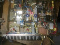
It could be my FRONT-END wiring fault... it sure looks a little bit funny
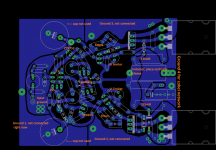
Yes, The PCB is 100% corresponding to NAP140, 180, 250 schematic, but drawn a little bit differently, VI limiter is included in PCB but not installed yet!! PCB copper layer thickness 18um.
The Inductor:
This inductor is less then 0.5uH in reality and was made from very THICK wire, so it won't affect damping factor(bass is accurate and goes deep down if necessary). 6mm diameter works best, as i have written here before.
Transistors:
Re-checked the package and found that 2N4401G's are from on-semi. These are installed into NAIM's LTP. scroll down for gain measurements.
TR4 emitter is 68R as in original.
TR3 emitter resistance is set to 565R, i cannot go higher, the sound becomes screaming and un-comfortable to the ears, but also, there is something added to the the overall sound, something cool i cannot listen to cuz of 2N4401 properties.
I have some fairchild and kec BC550C's and BC550B's too, i will try them as i get free time.
Specifications:
For correctness, FRONT END voltage is +/- 35V DC
OUTPUT stage voltage is +/-28V DC
Because of the metal case construction, it is very comfortable to configure NAIM's, easy and fast (Y)
Another thing is that ground are properly wired, no ground-loop's inside naim or TIDU34 circuit. There is possibility for switching inputs:
Transistor gain measurement:
I use this device to measure all three and two leg semiconductors!!:
TIP41C/TIP42C from fairchild: 48HFE % 178HFE
TIP41CG/TIP42CG from on-semi: 324HFE % 300HFE
I happen to have two types, 2N4401G ON-SEMI and 2n4401BU fairchild. ON-semi 330-426HFE, fairchild are all 286HFE.
ZTX 753 226 HFE
ZTX 653 172 HFE
2SC5200 are alll 98 HFE
One more comment about the H-140 and Naim.
H-140 booring, more FLAT compared to Naim = interesting with great potentials(it feels like it AMPLIFIES just the kind of instruments you WANT to hear lol, it makes up the naim i think very nice indeed).
Feedback:
You are correct, 2N4401 aren't good in naim LPT, they need much more current for correct operation.
TIP41CG/TIP42CG are not good too(very high gain), i will write the resistors gain measurements at the end of the message, please see and if possible place a comment.
Also, Before placing the NAIM boards into metal case, i checked them on laboratory +/- 30V PSU, they did not oscillate there with BC550C LTP transistors, i was making sure, that the boards work and configured bias first time, it worked very well.
You are about 99% correct of the wiring loose or smth, i tried to follow the naim wiring techniques.
It could be my FRONT-END wiring fault... it sure looks a little bit funny
Yes, The PCB is 100% corresponding to NAP140, 180, 250 schematic, but drawn a little bit differently, VI limiter is included in PCB but not installed yet!! PCB copper layer thickness 18um.
The Inductor:
This inductor is less then 0.5uH in reality and was made from very THICK wire, so it won't affect damping factor(bass is accurate and goes deep down if necessary). 6mm diameter works best, as i have written here before.
Transistors:
Re-checked the package and found that 2N4401G's are from on-semi. These are installed into NAIM's LTP. scroll down for gain measurements.
TR4 emitter is 68R as in original.
TR3 emitter resistance is set to 565R, i cannot go higher, the sound becomes screaming and un-comfortable to the ears, but also, there is something added to the the overall sound, something cool i cannot listen to cuz of 2N4401 properties.
I have some fairchild and kec BC550C's and BC550B's too, i will try them as i get free time.
Specifications:
For correctness, FRONT END voltage is +/- 35V DC
OUTPUT stage voltage is +/-28V DC
Because of the metal case construction, it is very comfortable to configure NAIM's, easy and fast (Y)
Another thing is that ground are properly wired, no ground-loop's inside naim or TIDU34 circuit. There is possibility for switching inputs:
- Audio input to NAIM directly
- Audio input to Preamp and then NAIM
Transistor gain measurement:
I use this device to measure all three and two leg semiconductors!!:
TIP41C/TIP42C from fairchild: 48HFE % 178HFE
TIP41CG/TIP42CG from on-semi: 324HFE % 300HFE
I happen to have two types, 2N4401G ON-SEMI and 2n4401BU fairchild. ON-semi 330-426HFE, fairchild are all 286HFE.
ZTX 753 226 HFE
ZTX 653 172 HFE
2SC5200 are alll 98 HFE
One more comment about the H-140 and Naim.
H-140 booring, more FLAT compared to Naim = interesting with great potentials(it feels like it AMPLIFIES just the kind of instruments you WANT to hear lol
, it makes up the naim i think very nice indeed).Attachments
Last edited:
EDIT: I have just replaced TIP41/42 CG transistors with BD139 and BD140.
Re-measured the TIP41CG, HFE 304
Re-measured the TIP42CG, HFE 424 what...
Manufacturer, ON-SEMI, they are original. Care needs to be taken to use them... i am sure these are pretty HI-END stuff.
BD's that went into NAP circuits are : (they are very similar to MJE253/243's.)
BD139, HFE 125
BD140, HFE 178
Manufacturer: ST microelectronics, packed in anti-static package. These are also from TME and are very dirty cheap.
Naims are fully on now, i had to set bias(crank potentiometer even further)
BIAS now 5mV per output resistor.
ALL the unsatisfing frequencys are gone lol, easier to listen, piano notes do not PEAK and produce warmer sound, but fowardness is gone somewhere...
I think i have to play with TR3 emitter resistance and re-adjust VAS-DRIVER base filter networks !!
As we can see, MJE253/MJE243 would be the best choise for drivers. HFE matters alot.
Last edited:
Hi Rensli. It seems you have been busy experimenting and that's great, you learn something useful each time you measure and compare circuit changes systematically. Unfortunately, I think you have problems using that Mega 328 tester. I have 2 similar testers myself but whilst they read similar to each other, they give very different results to Hfe test circuits with correct (much higher) bias current, as you see recommended in datasheets for the particular transistor types.
The figures you measure for Hfe would be OK if you were testing small signal transistors but not for medium or larger power transistors. With a more appropriate current for a power transistor, like 0.1 - 1A, you begin to see more correct Hfe readings. I doubt if there are any real TIP41/42 transistors with Hfe much higher than specified max. in datasheets. Here are ST Micro versions of TIP41/42 datasheets. See graphs of hFE v Collector current at 2.1 here: http://www.farnell.com/datasheets/1700358.pdf
The suffix A,B,C for power transistors isn't the same as the A,B,C used with small signal types. For example, BC550A,B,C means different Hfe ranges but TIP 41A,B,C means different Vceo rating (max. Collector-Emitter voltage). That's actually 60,80 or 100V - confusing, eh?
In a typical emitter-follower power amplifier, there will always be a significant bias current flowing in the driver transistors to ensure they operate mainly in class A so really, measuring power transistor Hfe at collector currents of only 1mA or so is a waste of time.
Here is a DIY Hfe tester design for power transistors by Geoff Moss (Author of The Class A Audio Site) which is easy to understand and the article discusses Hfe measurement requirements too: hFE Tester for NPN Power Transistors
I have a mega328.
I found that it gives identical readings on many devices.
It seems to have some bit depth limitation in converting analogue measurement results into bits and then displaying those bits as useful information.
It is great for identifying components and identifying component leadouts.
But, when it tells me that all the hFEs are 116 or 137 or 201 for 100 devices, I don't believe it !
Same for Vbe and lots of other parameter readouts.
- Home
- Amplifiers
- Solid State
- NAP-140 Clone Amp Kit on eBay