Mooly said:Going crosseyed looking at that. They are 5532,s not 5534 in the player. Pin 5 does not look connected on the layout.
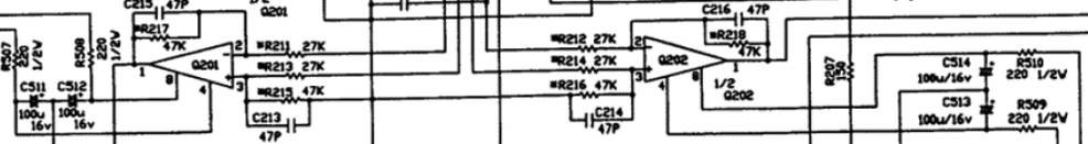
Pin 5 of Q201/202 is connected to ground....
Mooly said:
Edit, If they are 5532 then there are 8 individual OpAmps in there, the filter for the player shows 4. So how are they connected. The image is not really clear enough.
Service Manual at...
")
http://www.hifiengine.com/manuals/nad/5420.shtml
Mooly said:That accounts for six ? I think 2 missing ?
Unused perhaps
LOL....
Effectively Q203 and Q204 are only half used... (pins 3, 2, 1 )
Tube_Dude said:LOL....
Effectively Q203 and Q204 are only half used... (pins 3, 2, 1 )
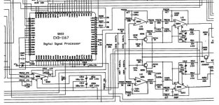
I believe you are correct. The power supply connections for Q201 & Q202 are on the left side of the schematic, under the MASH and DSP chips. See attached image.
Maybe it was easier and cheaper for NAD to purchase lots of NE5532, and waste a few halves, rather than mixing NE5532 and NE5534 parts on the one PCB.
Attachments
glennb said:
Maybe it was easier and cheaper for NAD to purchase lots of NE5532, and waste a few halves, rather than mixing NE5532 and NE5534 parts on the one PCB.
Yep!
I have seen sometimes dual op-amps only half used ....
Ah, thanks everyone for figuring that out. I hadn't realized that layout could be presented in that way.
Mooly, your expression tells me you might not waste time on the setup but my options seem to be ...
a) leave it as it is
b) replace all four, maybe with LM4562s or perhaps use 2 X OPA2107 and 2 X LM4562
c) use Burson discrete dual opamps in one or both positions
Any thoughts on these ideas?
parrot
Mooly, your expression tells me you might not waste time on the setup but my options seem to be ...
a) leave it as it is
b) replace all four, maybe with LM4562s or perhaps use 2 X OPA2107 and 2 X LM4562
c) use Burson discrete dual opamps in one or both positions
Any thoughts on these ideas?
parrot
Hi,
The Mooly option (I like that ) I think would be this. As you point out at the start you have limited experience of this kind of thing, so you need to get a feel for what it's about and hopefully get some improvement along the way without problems. There was a thread a while back about these Burson OpAmps and the person concerned had a lot of problems with them.
What I would do is this, remove the 5532's and fit sockets for now. Get a few different OpAmps to try as drop in replacements and see what you think.
I would really recommend you try the OPA2604. Yes there are newer devices now that others swear by but these take some beating for this kind of application. The distortion spectrum they produce is mainly even harmonic which is "pleasing" to the ear. I used these (The OPA604 single version) in my Micromega as a replacement for 5534's, and I can't recommend them highly enough.
I know you won't be dissappointed ! And what is also good fun for a real reality check--- get some dual 741s'--- 4558 comes to mind and try those. Just for fun- it's a real leveler. The very worst (and you decide how good or bad it REALLY is 35 after years or so).
If you like what you hear (probably not the 4558 but you never know), I would then remove the sockets and fit permanently. As you say,there is nothing to stop you trying two different types together either. TLO72's are suprisingly good as well.
Use solder braid to remove the old ones, and have fun with it.
Last bit of advice, listen long enough to make a decision, experimenter expectation comes into play hear, listen over a couple of days to each change, and to a lot of different music to tell.
Regards Karl
The Mooly option (I like that
) I think would be this. As you point out at the start you have limited experience of this kind of thing, so you need to get a feel for what it's about and hopefully get some improvement along the way without problems. There was a thread a while back about these Burson OpAmps and the person concerned had a lot of problems with them.What I would do is this, remove the 5532's and fit sockets for now. Get a few different OpAmps to try as drop in replacements and see what you think.
I would really recommend you try the OPA2604. Yes there are newer devices now that others swear by but these take some beating for this kind of application. The distortion spectrum they produce is mainly even harmonic which is "pleasing" to the ear. I used these (The OPA604 single version) in my Micromega as a replacement for 5534's, and I can't recommend them highly enough.
I know you won't be dissappointed ! And what is also good fun for a real reality check--- get some dual 741s'--- 4558 comes to mind and try those. Just for fun- it's a real leveler. The very worst (and you decide how good or bad it REALLY is 35 after years or so).
If you like what you hear (probably not the 4558 but you never know), I would then remove the sockets and fit permanently. As you say,there is nothing to stop you trying two different types together either. TLO72's are suprisingly good as well.
Use solder braid to remove the old ones, and have fun with it.
Last bit of advice, listen long enough to make a decision, experimenter expectation comes into play hear, listen over a couple of days to each change, and to a lot of different music to tell.
Regards Karl
Besides playing the opamp types, there are lots of other mods which could improve the sound. To name just a few:
- Add film bypass caps across all the electro caps associated with the power supply pins of the opamps (C511-518) and also the input & outputs of the voltage regulator ics (C501-504). This CD player is completely devoid of film cap bypasses on the analog power supply rails, its a wonder its stable.
- Put film cap bypasses on C229 & C230 audio output coupling electro caps (or get rid of them completely)
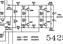
- Disconnect the mute circuitry (emitters of Q207 - Q210)
- Upgrade the quality of the all the film caps in the active filters (C217-228). They are all garden variety polyesters.
- Add film bypass caps across all the electro caps associated with the power supply pins of the opamps (C511-518) and also the input & outputs of the voltage regulator ics (C501-504). This CD player is completely devoid of film cap bypasses on the analog power supply rails, its a wonder its stable.
- Put film cap bypasses on C229 & C230 audio output coupling electro caps (or get rid of them completely)
- Disconnect the mute circuitry (emitters of Q207 - Q210)
- Upgrade the quality of the all the film caps in the active filters (C217-228). They are all garden variety polyesters.
I'm sort of overwhelmed ...
Mooly and Karl,
thanks for all the advice and ideas. Its very generous of you to give time and thought to his matter. I'd been feeling rather stupid about not seeing the "other" parts of the opamps but the circuit and the possibilities make more sense now.
Yes, the non-Burson approach looks prudent so I'll work on that along with the caps, the socket and the mute circuitry. Hmmm ... should keep me quiet for some months
thanks again
parrot
parrot said:Hmmm ... should keep me quiet for some months
thanks again
parrot
Some months, get e'm fitted 1 hour tops. And as Glenn say's, there is plenty you can do, just take it slow and evalute each change carefully.
Karl
ooops, thanked Karl twice but inadvertently missed Glenn.
Thanks Glenn,
that's not really a huge amount of work though I'll take my time particularly on the listening tests.
Caps first I guess, which should add to stability when trying out different opamps.
Exciting ... thanks
parrot
Thanks Glenn,
that's not really a huge amount of work though I'll take my time particularly on the listening tests.
Caps first I guess, which should add to stability when trying out different opamps.
Exciting ... thanks
parrot
Summary after some checking:
PART A:
a) remove C229 & C230 [I've got more than adequate good quality input caps on my pre-amp so that option should be quite safe]
b) replace the existing active filter C217 to C228 polyesters ... no problem!
c) 1/100th bypass, 1uf film caps for power supply caps C511 to C518. That's a fair stack of caps! Does the 1/100the rule apply here?
d) C501/C502 are 2200uF. C503/C504 are 1000uF. What value film caps will do the trick here?
d) disconnect mute circuit emitters Q207 to Q210. OK, easy to do but could I ask what this part of the circuit [attached] was doing? Is it "the appendix" perhaps?
PART B:
When things have settled in a little, try the various opamps options.
parrot
Attachments
Hi,
Part "D" of your question, these transistors provide a mute function. When they turn on the output is "shorted" It's up to you whether you can live with any noises produced-- switch on/off, between track searching etc. If you are really keen you could replace these with a small relay instead-one for each channel.
I would listen with and without them connected- if you really can't tell a difference leave in. As they are in parallel (sort of !)why not remove one set, probably the ones nearest the output would be best and try that.
The trouble with replacing caps is that unless your replacements are absolutely physically identical, it all ends up looking messy + there is the possibility of any "legs" actually picking up noise, particularly in the audio and filter stages. Just be aware- to be honest the first thing I would do is swap the I/C's, you won't have any stability problems with the types mentioned, even in sockets.
Any electroylitics on the rails, if they are of a 5mm lead pitch I tend to put a 0.1mfd surface mount type on the PCB directly underneath. Easy to do and looks original. If you are neat at soldering you can add a 0.1mfd ceramic or polycap (legged variety) across pins 4 and 8 of the I/C directly soldering as near to the top of the leg as poss and without letting solder run down the rest of the pin. Bend the legs to shape first, these type of parts crack and damage easily. Clean the pins with a cotton bud and iso to remove flux and they should still fit the sockets perfectly. I think the I/C's will give you the biggest (obvious change) thats why I suggested these first.
Have fun and get e'm fitted. Let us know what you think as well when it's done.
Regards Karl
Thanks again Karl,
the help is greatly valued. I'll work through it and report back. I've replaced the output caps with wire links and gained a useful improvement but I'll order a small clutch of opamps with some caps and move on to the serious stuff.
Many of the caps in the original work are somewhat Leaning-Tower-of-Pisa so I can probably only improve on that. My soldering is quite good, it's just my electronic knowledge that's limited.
I will also be assiduous with my post-work cleaning around the opamps.
parrot
Sounds good If any caps have to be "stood up" always connect the "longest" wire to the lowest impedance point, for example the output of an OpAmp or ground. Also with some caps like tubular polys etc you can see which leg of the cap is the "outer" part of the foil and which the "inner" Again connect the "outer" to the lowest impedance point and you gain by being able to use the "shielding" effect to stop the cap itself picking up noise.
Regards Karl
If any caps have to be "stood up" always connect the "longest" wire to the lowest impedance point, for example the output of an OpAmp or ground. Also with some caps like tubular polys etc you can see which leg of the cap is the "outer" part of the foil and which the "inner" Again connect the "outer" to the lowest impedance point and you gain by being able to use the "shielding" effect to stop the cap itself picking up noise.Regards Karl
- Status
- This old topic is closed. If you want to reopen this topic, contact a moderator using the "Report Post" button.
- Home
- Amplifiers
- Chip Amps
- NAD 5420 CDP opamps