"If any caps have to be "stood up" always connect the "longest" wire to the lowest impedance point"
&
"connect the "outer" to the lowest impedance point"
Great tips, thanks!
I've been wondering, with regard to the NAD audio output section, if I could delete that last pair of opamps [Q203 & Q204] and take my output from Q201 & Q202. I've got plenty of gain from a Burson Buffer and my pre-amp so in a way, less gain would be good.
If this is simple ... great, if it raises all manner of tricky issues, then I'll keep things as they are in terms of the opamps.
parrot
parrot said:[B...I've been wondering, with regard to the NAD audio output section, if I could delete that last pair of opamps [Q203 & Q204] and take my output from Q201 & Q202. I've got plenty of gain from a Burson Buffer and my pre-amp so in a way, less gain would be good.
If this is simple ... great, if it raises all manner of tricky issues, then I'll keep things as they are in terms of the opamps.
parrot [/B]
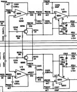
Q203 and Q204 are low pass active filters which remove high frequency digital-to-analog conversion artefacts from the signal. It is possible to avoid the filter, but the following preamp and power amp may not like the added "noise". Its worth a try though....
R227-234, Q205-206, C223-224 form the de-emphasis circuit. It's turned on and off by switching the the junction of R239/240 between +V and 0V.
If you take the output signal from either end of R227/228 any CDs that were recorded with emphasis ON will not have the correct equalisation, and they'll sound like s**t.
Attachments
Hi,
In a word "No"") Q203/4 and components form a low pass filter that is needed to "reconstruct" the audio and to remove HF noise from the DAC's. Do you have an oscilloscope by the way ? There's a bit more as well, Q205/6 are for discs recorded with pre emphasis. They switch C224 & R232 into circuit to alter the filter response. That said very few ( I believe) discs now use this, it was mainly Japanese discs in the early days that did, that said I do have a few in my collection that use it.
Q203/4 and components form a low pass filter that is needed to "reconstruct" the audio and to remove HF noise from the DAC's. Do you have an oscilloscope by the way ? There's a bit more as well, Q205/6 are for discs recorded with pre emphasis. They switch C224 & R232 into circuit to alter the filter response. That said very few ( I believe) discs now use this, it was mainly Japanese discs in the early days that did, that said I do have a few in my collection that use it.
In a word "No"
Q203/4 and components form a low pass filter that is needed to "reconstruct" the audio and to remove HF noise from the DAC's. Do you have an oscilloscope by the way ? There's a bit more as well, Q205/6 are for discs recorded with pre emphasis. They switch C224 & R232 into circuit to alter the filter response. That said very few ( I believe) discs now use this, it was mainly Japanese discs in the early days that did, that said I do have a few in my collection that use it.Mooly said:Posted together again
Wow, its remarkable how similar our posts were!
Glenn & Karl,
your unanimity gives a strong sense of direction.
No, I don't have a scope and at the moment I'm struggling between trying to keep it simple and delving more deeply into how things work.
I'm still processing the information you've given me but the NAD circuit leading up to the output at least makes some sort of sense to me now.
From what you've said, meddling with the Q203/Q204 opamps doesn't sound likely to lead anywhere particularly useful. The de-emphasis circuit looks as though it might not be useful, most of the time but it seems there might be the odd occasion when it is, so for now I don't think I'll fiddle with it.
Do the different roles of Q202/Q201 and Q203/Q204 have implications for the types of opamp to try in these positions? Is it worth experimenting with both sets or could I be better off just to fit say OPA 2604s in one set of positions and experiment more with the other, if that makes sense?
parrot
Hi.
I think you really have to try it and see. The OPA2604 is a FET OpaAmp, the NE 5532 were a more conventional "no fet" type. You need to keep it all "as is " really, particularly without a scope to see the effect of any changes. You can freely swap the OpAmps, trying diferent ones in each posistion.
Bit of a hurried answer that.
Edit-- Have a look on Wikipedia, search "opamps" and "butterworth filters" and "sallen and key" there are various links off these that might help your understanding.
Look here www.burr-brown.com The link will redirect you to Texas Instruments who now own Burr Brown. In the top right box under part number enter opa2604. When that page loads click on opa2604 under the part numbers offered. You can now download the pdf data sheet for this I/C . The applications given might help you make sense of it all more, and it describes the IC in detail. The TL072 is a Texas part, check that out as well, the LMxxxx are National Semiconductor.
ok ... that all makes sense.
I've looked at opamps in Wiki but I'll have a look at Butterworth etc.
Some of this is way above my head but at this point it seems that trying a few different opamps will be safe and interesting and that's the goal.
So ... thanks again Karl. I'll order a few opamps, solder in some sockets for testing and see how it goes [in the middle of building a sub at the moment so I'm a bit ahead of myself here but it gives me time to think about options].
parrot
I would be interested to know what YOU think of the different I/C 's . The OPA2604 (and 604) certainly do it for me. They made my MicroMega Stage 2 really sing. I can't fault them. I also used them in the preamp section of my latest amp build.
As I said earlier though, try different ones and do try a couple of 4558's, they cost peanuts, they are as bad as it comes ( for audio), and it's just really interesting to see how far we have come ( or not ! ).
It's a bit like washing powders. . In the 80's it seemed that a new improved version was advertised every other week, and this went on for years, so by definition, the first ones must have been spectacularly bad.
As I said earlier though, try different ones and do try a couple of 4558's, they cost peanuts, they are as bad as it comes ( for audio), and it's just really interesting to see how far we have come ( or not ! ).
It's a bit like washing powders.
. In the 80's it seemed that a new improved version was advertised every other week, and this went on for years, so by definition, the first ones must have been spectacularly bad.LOL ... gotta say the idea of trying something "as bad as it comes" has a certain quirky appeal.
I'm looking forward to doing a bit of swapping. Having replaced the output caps with wire, it seems the longest part of any process is taking the box apart though with the sockets in place that won't be necessary.
parrot
I'm looking forward to doing a bit of swapping. Having replaced the output caps with wire, it seems the longest part of any process is taking the box apart though with the sockets in place that won't be necessary.
parrot
Make sure you use solder braid to remove the old I/C's and this maybe sounds obvious but we have all done it , when you try and remove I/C/s from sockets prise a bit at a time each end. Try and do it in one go or using fingers and it will flirt out, pins at 90 degrees, probably embedded in your finger. We have all done it
Edit, I will add, when you remove a part clean the pcb (solder) with a cotton bud and iso or meths to get any old flux off. Any mods you do should be indestinguisable from a factory fitted part.
, when you try and remove I/C/s from sockets prise a bit at a time each end. Try and do it in one go or using fingers and it will flirt out, pins at 90 degrees, probably embedded in your finger. We have all done it Edit, I will add, when you remove a part clean the pcb (solder) with a cotton bud and iso or meths to get any old flux off. Any mods you do should be indestinguisable from a factory fitted part.
Hi,
Braid is easy, the secret is a hot iron with a large bit well tinned-pleanty of fresh solder on it.
Sounds mad but don't be afraid to add a little fresh solder to the braid as you actually apply it, the flux will help it all get sucked up instantly. Should take about 1.5 to2 secs total per pin on the IC, do each pin one at a time, bend the braid over the tip in a U shape and pull tight as you apply to the pin to unsolder.
- Status
- This old topic is closed. If you want to reopen this topic, contact a moderator using the "Report Post" button.
- Home
- Amplifiers
- Chip Amps
- NAD 5420 CDP opamps