Mooly,
Anything is possible, right? .
.
I've set my DMM to a max/min/avg feature, and I see some varying results with regards to AC voltage across the caps. When not playing any audio (or with no load), then the amp will hover around 0.01 to 0.03V AC. However, when playing audio through a load, I saw the "max" reading jump up over 1V many times and it crested up to just about 2.0V AC.
I'm not sure if this is enough to cause any issues, or if the varying results while audio is playing is enough to indicate a bad rectifier. For what it's worth, the cap that's not bulging displays the same AC swing.
With regards to DC voltage across the same cap, when audio is not playing, it hovers around 70V, as I said before. My mains typically stay around 122-124V. I assume that there could be a jump sometime when I wasn't looking, but I doubt it. When audio is playing into a dummy load (at very loud levels), I see the DC voltage across the main supply dip to 62-63V DC. I expect to see some droop, but does this seem excessive to you? Perhaps another clue?
I can see reason for changing the rectifier on a whim, but should I go for a higher-rated or faster rectifier? The current requirement is a KBL04 (400V, 4A). Mouser does not have those in stock right now, so I was looking at a KBL604 (400V, 6A). I know that will work fine, should I be looking at something else instead (like a faster switching rectifier)?
Anything is possible, right?
.I've set my DMM to a max/min/avg feature, and I see some varying results with regards to AC voltage across the caps. When not playing any audio (or with no load), then the amp will hover around 0.01 to 0.03V AC. However, when playing audio through a load, I saw the "max" reading jump up over 1V many times and it crested up to just about 2.0V AC.
I'm not sure if this is enough to cause any issues, or if the varying results while audio is playing is enough to indicate a bad rectifier. For what it's worth, the cap that's not bulging displays the same AC swing.
With regards to DC voltage across the same cap, when audio is not playing, it hovers around 70V, as I said before. My mains typically stay around 122-124V. I assume that there could be a jump sometime when I wasn't looking, but I doubt it. When audio is playing into a dummy load (at very loud levels), I see the DC voltage across the main supply dip to 62-63V DC. I expect to see some droop, but does this seem excessive to you? Perhaps another clue?
I can see reason for changing the rectifier on a whim, but should I go for a higher-rated or faster rectifier? The current requirement is a KBL04 (400V, 4A). Mouser does not have those in stock right now, so I was looking at a KBL604 (400V, 6A). I know that will work fine, should I be looking at something else instead (like a faster switching rectifier)?
I wouldn't think there was much point going for a faster rectifier tbh. A big slow and robust standard one is fine
Your mains voltage would have to rise to give well over 80 volts and for a substantial time period for it to damage the caps. The dip you see does sound a lot, particularly if its on music because that is far less demanding than sine testing.
DVM's can behave a bit erratically on AC ranges when there is a large DC component present. You would really to add a very low value resistor in series with the caps and measure the voltage across it using a scope.
I think you do have to change the bridge if only to eliminate it.
Hi,
I forgot to mention that also by installing the capacitors with the wrong polarity will cause the capacitor to bulged. Did you checked to make sure the caps are installed with the right polarity?. Just remove the cap and check the voltage polarity to see if they are install right.
I forgot to mention that also by installing the capacitors with the wrong polarity will cause the capacitor to bulged. Did you checked to make sure the caps are installed with the right polarity?. Just remove the cap and check the voltage polarity to see if they are install right.
They are 4-pin snap-ins, so there's no way to put them in wrong. I do have some some concern over the fact that the caps say "Do not connect" on two of the pins, but the NAD design has them connected. Maybe I'll snip off those pins before I risk another $10.
Also, I'm looking to replace the rectifier locally. I can find a KBU4G rectifier, which has the same specs as the recommended KBL04, but it has a hole in the center of the package for a heatsink mount. The original design has a solid package and no heatsink is used. So, would the KBU4G work fine to replace the KBL04 in this design?
Original KBL04 datasheet:
http://www.vishay.com/docs/88655/kbl005.pdf
Possible replacement KBU4G:
http://www.vishay.com/docs/88656/kbu4.pdf

I may be unraveling my own mystery.....
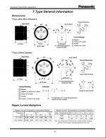
I just measured an unused Panasonic cap, and I noticed that there is a potential between the NC pins and the negative pin. There's also a slight amount of capacitance between all of the pins. So, the possibility of a connection problem exists.
In furthering my research, I see that the United Chemicon datasheet states:
"Use the blank terminals for mechanical support only. The blank terminals must not be connected to a solder trace on the PC board, but be electrically isolated from the negative or positive terminal."
This agrees with Panasonic, but doesn't explain why I'm seeing the issue on one cap and not the other.
However, when I found the EPCOS datasheet for 4-pin capacitors, it states:
"All pin holes must be drilled into the PC-board, since the unconnected pins serve as mountings. These pins must be soldered to isolated pads or pads with the same potential as the negative pole (solder pin and 4-pin snap-in terminals)."
Well, check out this photo of the NAD design. I used a red circle to highlight the location of the "bulging" capacitor and a yellow circle to highlight the location of the "good" capacitor:

Lo-and-behold there's a possible reason for one cap bulging and not the other. The "bulging" offender has one NC pin connected to its own negative pole, while the other NC pin is connected to the negative pole of the second capacitor. I.e., there's a chance for 140V of potential across that cap. This may explain why it bulges slowly....
The second cap (the one that doesn't bulge) has both NC pins connected to the same cap's negative pole - which is what the EPCOS datasheet recommends.
I'm thinking I'm going to pull the good caps I have left and snip off the NC mounting pins. Hopefully this will correct the issue!!
I just measured an unused Panasonic cap, and I noticed that there is a potential between the NC pins and the negative pin. There's also a slight amount of capacitance between all of the pins. So, the possibility of a connection problem exists.
In furthering my research, I see that the United Chemicon datasheet states:
"Use the blank terminals for mechanical support only. The blank terminals must not be connected to a solder trace on the PC board, but be electrically isolated from the negative or positive terminal."
This agrees with Panasonic, but doesn't explain why I'm seeing the issue on one cap and not the other.
However, when I found the EPCOS datasheet for 4-pin capacitors, it states:
"All pin holes must be drilled into the PC-board, since the unconnected pins serve as mountings. These pins must be soldered to isolated pads or pads with the same potential as the negative pole (solder pin and 4-pin snap-in terminals)."
Well, check out this photo of the NAD design. I used a red circle to highlight the location of the "bulging" capacitor and a yellow circle to highlight the location of the "good" capacitor:
Lo-and-behold there's a possible reason for one cap bulging and not the other. The "bulging" offender has one NC pin connected to its own negative pole, while the other NC pin is connected to the negative pole of the second capacitor. I.e., there's a chance for 140V of potential across that cap. This may explain why it bulges slowly....
The second cap (the one that doesn't bulge) has both NC pins connected to the same cap's negative pole - which is what the EPCOS datasheet recommends.
I'm thinking I'm going to pull the good caps I have left and snip off the NC mounting pins. Hopefully this will correct the issue!!
Last edited:
Continuing my research:
Cornell Dubilier Electronics has this to say about the NC pins:
" Use dummy terminals for mechanical support only. Make no electrical connection because they resistively connect through the electrolyte to the negative terminal."
Vishay says:
"Pin numbers 2, 3 and 4 (if present) should be free from the electrical circuit or connected to the minus terminal."
So yes - I'm going on a limb and guessing that this is my issue. Specifically since the electrolyte restively connects the NC terminals to the negative terminal, this could be a big issue for anyone with a NAD 2100 design that's replaced these caps. I'll change out the cap again (minus the NC pins connected) and let it run for a few days to see if the issue disappears!
Tauro - That agrees with the datasheet I saw. "DO NOT CONNECT". It's also plastered all over the cap. I just never figured that NAD would have screwed up the design, or that the capacitors would change such that the NAD design (or any design) became a problem.
I guess it's possible that NAD had Teapo (or whoever was their cap manufacturer) custom create a cap for them.....
I guess it's possible that NAD had Teapo (or whoever was their cap manufacturer) custom create a cap for them.....
Last edited:
Hi,
Do not forget that companies can order their capacitors with special specification depending on their applications. Just cut off the extra pins and see if it still bulged. Also some caps companies used those extra pins as a mechanical for holding large size capacitors to the board.
Do not forget that companies can order their capacitors with special specification depending on their applications. Just cut off the extra pins and see if it still bulged. Also some caps companies used those extra pins as a mechanical for holding large size capacitors to the board.
Just FYI -- I'm roughly 20 hours in with the changes (clipping off the NC pins), and I don't have any signs of bulging yet. Time will tell, but I think this worked. It only makes sense to me that if the electrolyte was providing a resistive connection to the negative pole and one of the NC pins was connected to -70V that the high-side cap would then have been exposed to about 140V potential.
Hopefully this saves time and headache for someone else
Hopefully this saves time and headache for someone else
Well, it's been about 48 hours now, and no bulging! So, I think I found the root cause and a work-around (snipping of the NC leads of the main caps).
I've been putting the amp through it's paces today, and it's pretty darned impressive given that I paid about $70 for it (shipped to my door) and another ~$80 in new caps, fets, and the like.
On the "normal" input, which passes through some filters and a volume control, the frequency response is approximately +0.1dB at 20Hz and -0.5dB at 20KHz. However, because of the passive filters they use, this varies slightly with the level. The distortion stays around the 0.02% region for most of the usable power and frequency.
The "lab" input, which goes straight into the amp, is where the magic happens. The frequency response is -0.05dB at 20Hz and -0.1dB at 20KHz. The distortion, however, is quite good. It's at 0.005% for nearly the entire frequency band and power levels. Even when I cranked it up to 65W/channel (8-ohms) with both channels driven, the distortion was less than 0.02%!!!
Not too shabby for a circa 1990 50W design that cost me about $150 and should last me another 20 years now.
I've been putting the amp through it's paces today, and it's pretty darned impressive given that I paid about $70 for it (shipped to my door) and another ~$80 in new caps, fets, and the like.
On the "normal" input, which passes through some filters and a volume control, the frequency response is approximately +0.1dB at 20Hz and -0.5dB at 20KHz. However, because of the passive filters they use, this varies slightly with the level. The distortion stays around the 0.02% region for most of the usable power and frequency.
The "lab" input, which goes straight into the amp, is where the magic happens. The frequency response is -0.05dB at 20Hz and -0.1dB at 20KHz. The distortion, however, is quite good. It's at 0.005% for nearly the entire frequency band and power levels. Even when I cranked it up to 65W/channel (8-ohms) with both channels driven, the distortion was less than 0.02%!!!
Not too shabby for a circa 1990 50W design that cost me about $150 and should last me another 20 years now
.- Status
- This old topic is closed. If you want to reopen this topic, contact a moderator using the "Report Post" button.
- Home
- Amplifiers
- Solid State
- NAD 2100 DC Offset