Milos could it be just the burn in of the components? How many hours do you have on your amp? I had similar issues until it reached 250-300 hours!
Actually the problem started after around 500hrs ( 5-6 days 10+ hours a day).
It sounded fantastic from the 1st power on.

Could be,but Milos is using components from Dario's bom and still have the same issues.
I use Panasonic FC in many different builds for PSU filtering and no sibilance problems.Sibilance is a form of distortion and hi quality parts like FC, just don't do it.
They can sound bright or sparkling, or whatever you want to call it but it is hard to believe that they would introduce distortion in this quantity.
I run nichicon PW on one ch. for C1-C2 and C6-C11, and still have the same sibilance as on the other ch. which is using nichicon muse in the same positions.
Nichicon PW are dark sounding caps and no way they can introduce sibilance.
I think Dario's new compensation network might be the cure or/and Zobel.
I'll give a few more days to burn in and then will try compensation and Zobel.
I use Panasonic FC in many different builds for PSU filtering and no sibilance problems.Sibilance is a form of distortion and hi quality parts like FC, just don't do it.
...
I run nichicon PW on one ch. for C1-C2 and C6-C11, and still have the same sibilance as on the other ch. which is using nichicon muse in the same positions.
Nichicon PW are dark sounding caps and no way they can introduce sibilance.
Panasonic FC/FM/FJ and Nichicon Muse FW and PW have magnetic leads and can sound harsh in a Myref, especially in locations C1, C2, C6, C9 and C11. Try a Pureism, Cerafine, Muse FG/KZ or Silmic II, and the difference will be apparent. Avoid low-ESR computer-grade caps like Rubycon ZL also.
There is no difference in sibilance, in my build, between ch. that is using magnetic leads caps (PW) and one that does not. The other ch. is using Silmic II for C9, C1-C2 are muse BP (bipolar) and c6-c11 are KZ- none with magnetic leads. Nichicon FW and PW are not MUSE caps at all, just standard for audio and low-ESR for switching supplys. As I written above, I would not describe this as harsh sound, more like subtle, but wrong eq.ing.
Apart from the troubled frq. range everything else is very good soft and smooth (partly thanks to AIKIDO buffer in front of it).
Cheers
Apart from the troubled frq. range everything else is very good soft and smooth (partly thanks to AIKIDO buffer in front of it).
Cheers
another v1.3 ultimate
(2 years later) I've finally managed to finish my 1.3 Ultimate , here's the concept and the result (hope you don't mind posting here)
All the best,
Bruno Henriques
(2 years later) I've finally managed to finish my 1.3 Ultimate , here's the concept and the result (hope you don't mind posting here)
All the best,
Bruno Henriques
An externally hosted image should be here but it was not working when we last tested it.
An externally hosted image should be here but it was not working when we last tested it.
Last edited:
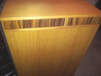
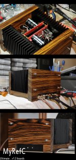
well thank you Bob, yes it's zebrawood, I had some pieces lying here for a long time awaiting for a project like this, it was all done without special tools, but with lot's of elbow grease, only treatment I gave it was several layers of teak oil (in between steel wool passes).
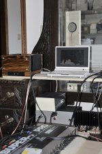
Sadly, the PS is just a grey/black dull box (for the time being) with a 225Va, some protection circuit (to check the mains Load, as here with the schuco plugs one can have it both on the left or the right side of the plug), fuse and a filter... I've used 2 CL-60 directly on the PGND connections to Earth on the amp side
You can see it on top of my other PS (the big box) for a P2P minimal gainclone (which I still have to finish casing)
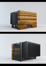
and the small GC will eventually turn into this (for appearance's sake)
ps sorry for the mess, as we are entering my "workshop" reign!!!
Sadly, the PS is just a grey/black dull box (for the time being) with a 225Va, some protection circuit (to check the mains Load, as here with the schuco plugs one can have it both on the left or the right side of the plug), fuse and a filter... I've used 2 CL-60 directly on the PGND connections to Earth on the amp side
You can see it on top of my other PS (the big box) for a P2P minimal gainclone (which I still have to finish casing)
An externally hosted image should be here but it was not working when we last tested it.
and the small GC will eventually turn into this (for appearance's sake)
An externally hosted image should be here but it was not working when we last tested it.
ps sorry for the mess, as we are entering my "workshop" reign!!!
The pics were working great last night. Some sort of glitch has appeared today. Admin help may be needed.
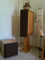
Z is my favorite wood and have planned a similar application for the BLAT. I used it as accent wood on the HT system used prior to the new Sunflowers. The first pic is a di-pole surround. Two matching subs are in storage. Last pic shows different design for inside of front mains.
Z is my favorite wood and have planned a similar application for the BLAT. I used it as accent wood on the HT system used prior to the new Sunflowers. The first pic is a di-pole surround. Two matching subs are in storage. Last pic shows different design for inside of front mains.
Attachments
Last edited:
here they go again
here, I've attached them (I'll ask here a mod to remove them from my last 2 posts, as I cannot edit them )
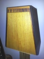
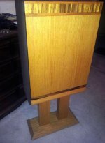
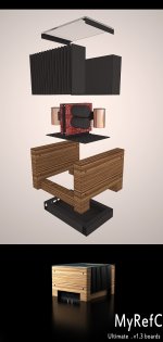
from left to right:
my concept for the revc casing, the "almost" finished box (minus the top glass), workshop mess (rev c and p2p gainclone in tests), the proposed casing for that minimal gc
I find that a simple finish (like teak oil) gives this sort of hard wood a beautiful grain, even if one has to apply it from time to time...
ps. Bob, Zebraw is one of my favourite too!
here, I've attached them (I'll ask here a mod to remove them from my last 2 posts, as I cannot edit them )
from left to right:
my concept for the revc casing, the "almost" finished box (minus the top glass), workshop mess (rev c and p2p gainclone in tests), the proposed casing for that minimal gc
I find that a simple finish (like teak oil) gives this sort of hard wood a beautiful grain, even if one has to apply it from time to time...
ps. Bob, Zebraw is one of my favourite too!
Attachments
Last edited:
Test Measurements?
I will be powering up my boards for the first time soon, and want to check I've not missed any pre-flight checks. So far, my list contains :-
Have I missed anything obvious?
Thanks
I will be powering up my boards for the first time soon, and want to check I've not missed any pre-flight checks. So far, my list contains :-
- Measure for shorts with amplifier unplugged - Already done this, and rail to rail, rail to ground, all have at least 100 ohm resistance, so no shorts.
- Use a light bulb tester on first power up.
- Measure voltage of the rails. Mine should read +/- 33.8 V as I'm using 24 V secondaries
- Measure voltage to the LM3886 pins. I believe the voltage at the pins should read +/- 33.8 V, however would someone please confirm that.
- Measure voltage to the LM 318. Again, I belive the voltage should be +/- 12 Volts at the pins, but confirmation would be good. I'm also not sure where to take the readings from. I know pin 7 is V+, and pin 4 is V -, however what pin/pad should I use to ground the dmm probe?
- Measure the DC offset on the speaker terminals. I believe anything less than a 100 Mv is acceptable
Have I missed anything obvious?
Thanks

Dario answered them but somehow the notice showed but the post didn't. Here is a try.
Here is the message that has just been posted:
***************
---Quote (Originally by westers151)---
I will be powering up my boards for the first time soon ---End Quote--- Fantastic!
---Quote (Originally by westers151)---
Measure voltage to the LM3886 pins. I believe the voltage at the pins should read +/- 33.8 V, however would someone please confirm that.
---End Quote---
Yes, it should be the same you measured on smoothing caps.
---Quote (Originally by westers151)---
Measure voltage to the LM 318. Again, I belive the voltage should be +/- 12 Volts at the pins, but confirmation would be good. I'm also not sure where to take the readings from. I know pin 7 is V+, and pin 4 is V -, however what pin/pad should I use to ground the dmm probe?
---End Quote---
You should expect 14.6VDC, not 12VDC.
You can use C102/C202 pads.
---Quote (Originally by westers151)---
Measure the DC offset on the speaker terminals. I believe anything less than a 100 Mv is acceptable ---End Quote---
Yes, acceptable but you should expect less than 20mv.
Usually it measures 13mV, initially, and after some days it will be less then 7mv.
- Status
- This old topic is closed. If you want to reopen this topic, contact a moderator using the "Report Post" button.
- Home
- Amplifiers
- Chip Amps
- MyRefC build guide