On a completely different note: has anyone else noticed that the Russ White schematic shows 24v as the output to the relay/muting circuit? Yet Bill P has calculated, and I have measured in a working amp, 16.7v there because of the size of R14. I cannot find Mauro's original Page 2 of his schematic. Is there a value given that is different? Bill P, have you built a working amp with the smaller R14, yielding higher voltage? Does the relay mute circuit still work okay? Perhaps the voltage was lowered there to obtain a faster drop out of the relay at power off. Do you hear any noises when shutting off the amp with higher relay voltage? Some of these value changes were made on the fly, and perhaps the schematic should show 16v, or perhaps somebody miscalculated and R14 really is too big.
Following Bill's recommendation I built mine with 100R at R14 for 25V secondaries - I get 23.7v for the relay circuit.
Cheers
Geoff
and what voltage just before the relay is activated by it's driver transistor?
I see your point. I measured once the circuit was stable. Just looking at the simple bits I can see that reducing R14 will reduce the rise time for the voltage across C14. This could lead to a brief period (at switch on and before Q1 switches the relay) when the voltage far exceeds 24v.
Bill, did your Spice simulations look at this question?
Cheers
Geoff
Omron specifies the maximum coil voltage at 170% of nominal or 40.8 volts for the 24 volt relay. This is noted to not be a continuous rating so it can be taken to be a start up transient limit.
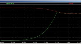
Relays are not precision components and Omron lists a 10% variation in coil resistance (and therefore coil current) as part of normal production. The coil resistance also rises 0.4% for each degree Centigrade of temperature rise. Given this information, I tried to keep the coil voltage within 10% of rating, 21.6V - 26.4V. The Spice simulation shows a 26.2 volt peak across the relay initially. It would have been 30 volts if the circuit applied the coil voltage instantaneously but it does not. It takes about 0.2 seconds for C16 to charge up to the point that the transistors Q1 and Q2 have enough base current to turn the relay on. During the charge time the supply voltage drops from 30 volts to 26.2 volts and that is the highest voltage the relay coil sees.
The Spice results are attached, green trace is relay coil voltage and red trace is the 24V supply rail. The vertical scale is 3 volts/division and the red trace starts out at 30 volts at the left side of the plot.
Attachments
I have almost finished my amp.
I hace if inside a case well fitted, It yet needs to be fixed right. The enclosure with allocate another two channels. They are a chipamp.com kit, which sounds very nice. I will be able to make fast direct comparisons between one standar topology with "standar" components (although very good ones: panny FM, dale resistors, wimas...) and Mauro's topology with high end components.
I have my tantalum resistors already fitted and soldered in. I am trying to listen carefully, but I don't know if I am able to discern such a difference. I am not any high end audiophile tester, so I would need thousands of hours listening a system to be able to difference it with such a precision. Only two resistors in the signal path, and both of them were previously very good ones, no less than PRPs.
At first, I would say that I don't hear any difference, maybe a bit more of clarity. But I am not sure at all, sorry.
Maybe is a change so so small that not everybody is able to discern it. Or maybe it doesn't produce any change at all to put other two high end resistors.
Thank you very much Uriah for giving me the chance to try them and being part these experiments.
I will take some photos as soon as I get back my camera.
Regards,
Regi
I wish I would have a whole system entirely made of tantalums. All stages, all signal paths. And having besides another system made of something more standard, like Vishay Dales.
Hearing to both, we could be able to perceive these differences. Maybe. Or maybe not. But the tantalum's one would worth its weight in gold
Hearing to both, we could be able to perceive these differences. Maybe. Or maybe not. But the tantalum's one would worth its weight in gold
For anyone needing instructions on how to build their LDR attenuator
Here are some instructions for completing the Mount and Balance board with LDRs and 5VDC supply.
Uriah
Lightspeed Instructions
Here are some instructions for completing the Mount and Balance board with LDRs and 5VDC supply.
Uriah
Lightspeed Instructions
Last edited:
very nice detailed instructions, with your permission I will add them to the documentation archive and upload.Here are some instructions for completing the Mount and Balance board with LDRs and 5VDC supply.
Uriah
Lightspeed Instructions
Regards,
Regi
- Status
- This old topic is closed. If you want to reopen this topic, contact a moderator using the "Report Post" button.
- Home
- Amplifiers
- Chip Amps
- MyRefC build guide