Thankyou, Troy kind words indeed,Ye well spotted the rca,s come with two different coloured insulators.I've been listen to it for 2 days now and it keeps getting better it started off quite bright in the highs and bass was a bit weak but today it's starting to sound alot more rounded and very accurate, bass is very tight.
Regi cant wait to yours boxed up ..")
Regi cant wait to yours boxed up ..
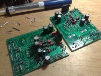
Before building the new GB MyRef I wanted to test the new components and some further upgrades too so I've started desoldering components from my old MyRef... result? Screwed-up PCBs...
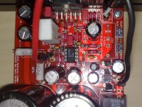
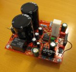
Well I've recovered most of the components (Elcos, Relay, some film caps...) and mounted all on two of the new PCBs (partially populated with PRPs, and carbon shunts).
But this time I've soldered sockets from the start and so I've the possibility to test:
C4, C1, C2 (LM3886 bypass)
C5 (diodes filtering)
C7, C6, C11 (LM318 bypass)
C9, C21 (feedback filtering)
C10, C12 filtering
C34 LM318 compensation
R12, R13 input resistors
R3 output resistor
Oops sockets out of stock... when others arrive I'll also socket R10 and R11.
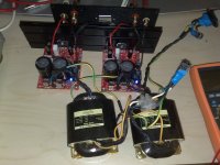
How it sounds? Great!
Better than my previous one? Yes, a bit, thanks to carbon shunts and a 16V 200uF BG STD too (C9).
And nice improvements over my previous one are also the MKP2 in C7 and MP915 in R3
Did I found some better component already? Sure!
So stay tuned...
Just one early suggestion... use a FKP2 in C12 and carbon shunts (Takman REX are perfect), you wont regret...
One final note: absolutely connect Power Ground to the star ground!
In my previous one I didn't and when inputs were disconnected hum was present and also my ampli was sensible to power spikes, well it seems they're gone...
Well I've recovered most of the components (Elcos, Relay, some film caps...) and mounted all on two of the new PCBs (partially populated with PRPs, and carbon shunts).
But this time I've soldered sockets from the start and so I've the possibility to test:
C4, C1, C2 (LM3886 bypass)
C5 (diodes filtering)
C7, C6, C11 (LM318 bypass)
C9, C21 (feedback filtering)
C10, C12 filtering
C34 LM318 compensation
R12, R13 input resistors
R3 output resistor
Oops sockets out of stock... when others arrive I'll also socket R10 and R11.
How it sounds? Great!
Better than my previous one? Yes, a bit, thanks to carbon shunts and a 16V 200uF BG STD too (C9).
And nice improvements over my previous one are also the MKP2 in C7 and MP915 in R3
Did I found some better component already? Sure!
So stay tuned...
Just one early suggestion... use a FKP2 in C12 and carbon shunts (Takman REX are perfect), you wont regret...
One final note: absolutely connect Power Ground to the star ground!
In my previous one I didn't and when inputs were disconnected hum was present and also my ampli was sensible to power spikes, well it seems they're gone...
Attachments
Great work, guys! It's so nice to see some completed amps; nicer still to learn that they sound good. You will get even better sound when the BG fully forms after a hundred or so hours of run time. Don't forget to experiment with better power cords, as this amp responds more than many big discrete designs.
Dario, thanks for reporting on your better components, and teasing us that you have even more parts to try. Please describe in detail your grounding scheme. Does it really eliminate line spike noise? If so, I will certainly convert mine the same way.
Does anyone still doubt that the name of this little amp is perfectly apt? Will it be your "ref"?
Peace,
Tom E
Beautiful Build Shark!!
Regi, Try sand paper on those tantalums to get the point to fit the hole. Maybe we will have to redo the boards at some point this year so we can all try a nicely sized board with whatever new BOM we all come up with. I wont be doing another BOM buy thats for sure!! but boards are easy.
Dario, You got your stuff faster than I expected. Shipping to Italy often takes over a month. Great to see you have them.
Uriah
Regi, Try sand paper on those tantalums to get the point to fit the hole. Maybe we will have to redo the boards at some point this year so we can all try a nicely sized board with whatever new BOM we all come up with. I wont be doing another BOM buy thats for sure!!
but boards are easy.Dario, You got your stuff faster than I expected. Shipping to Italy often takes over a month. Great to see you have them.
Uriah
You might be referring to tying power ground to Earth (protective earth) ground. The one from de IEC socket. If not, I consider the "star ground" to be the one onboard, between the 2 big filter capacitors, so this is already Power ground too.One final note: absolutely connect Power Ground to the star ground!
In my previous one I didn't and when inputs were disconnected hum was present and also my ampli was sensible to power spikes, well it seems they're gone...
Anyway, has anyone experimented with X1 or Y1 capacitors on the mains socket? I am aiming to make the last improvements to this reference amp.
I will try to sand them, and if I am able that will be a nice step. thanks for the recommendation.
You might be referring to tying power ground to Earth (protective earth) ground. The one from de IEC socket. If not, I consider the "star ground" to be the one onboard, between the 2 big filter capacitors, so this is already Power ground too.......
A CL60 from that star ground on the PCB to the chassis would be the ideal way to ground the floating power supply.
What will be the differences compared to a resistor or just nothing? Or even a plain wire?A CL60 from that star ground on the PCB to the chassis would be the ideal way to ground the floating power supply.
Dario, You got your stuff faster than I expected. Shipping to Italy often takes over a month. Great to see you have them.
Hi Uriah,
the packet arrived last week... but last week I was very busy...
But now I'm out of PCBs... any left?
Dario, thanks for reporting on your better components, and teasing us that you have even more parts to try.
The test bench is for both confirm the advantage that 'exotic' parts gives and also for testing some new/alternative parts (like Mills in R3, carbon film shunts, BG vs Silmic, MKS2XL in place of elcos, alternative PS bypass caps)
Preliminary tests are interesting, particularly about PS bypassing and MKS2XL...
Please describe in detail your grounding scheme. Does it really eliminate line spike noise? If so, I will certainly convert mine the same way.
You might be referring to tying power ground to Earth (protective earth) ground. The one from de IEC socket. If not, I consider the "star ground" to be the one onboard, between the 2 big filter capacitors, so this is already Power ground too.
I've simply connected the PGND of each MyRef board to the star ground (also safety ground is connected to the star).
Probably I will further experiment using the ESP ground breaker.
So far I haven't heard a single spike (the varistor is still in place too).
Tom, it's very a simple mod, just try it.
Anyway, has anyone experimented with X1 or Y1 capacitors on the mains socket? I am aiming to make the last improvements to this reference amp.
My MyRef is using from the start a Y2 cap across live and neutral and from three months ago also a varistor.
I can't hear any effect on sound. Which is good to me...
What will be the differences compared to a resistor or just nothing? Or even a plain wire?
A plain wire will tie the public utility system directly to your "isolated and pure" signal ground.
A resistor is a current limited device. The circuit is never right if resistors are burning which would happen if certain conditions were raised in the amp.
A CL60 is a reactive component. It acts like a "slightly" resistive path ( 10 Ohms iir)during normal operation but an open in times of a catastrophic event not interfering with the normal design / function of the circuit / amp.
A plain wire will tie the public utility system directly to your "isolated and pure" signal ground.
Hi Troy,
PGND is connected to AGND via R11 (1 Ohm) so the latter is already isolated, isn't it?
Capacitors and Inductors are reactive components. The CL-60 is a negative temperature coefficient resistor. At room temperature it is about 10 Ohms. During a fault the CL-60 heats up and the resistance drops thus forming a lower resistance connection to ground (less than 1 Ohm). During normal operation there is essentially no current in the CL-60. The maximum continuous current rating for the CL-60 is 5 amps which shoud be enough to blow fuses in the amplifier, CD player, or preamp, depending in where the fault is. Higher peak currents can also be handled by the CL-60 if one of the pieces of equipment has a larger fuse rating.
Hi Troy,
PGND is connected to AGND via R11 (1 Ohm) so the latter is already isolated, isn't it?
1 Ohm is sufficient if the PGND is left floating as Mauro had designed.
If you tie the PGND to chassis then "I PERSONALLY" (MY OPINION) don't think that is enough isolation from the public utilities (pu) polluted source.
In that regard I think Mr. Pass hits it right on the mark by using the CL60 to tie PGND to chassis.
Capacitors and Inductors are reactive components. The CL-60 is a negative temperature coefficient resistor. At room temperature it is about 10 Ohms. During a fault the CL-60 heats up and the resistance drops thus forming a lower resistance connection to ground (less than 1 Ohm). During normal operation there is essentially no current in the CL-60. The maximum continuous current rating for the CL-60 is 5 amps which shoud be enough to blow fuses in the amplifier, CD player, or preamp, depending in where the fault is. Higher peak currents can also be handled by the CL-60 if one of the pieces of equipment has a larger fuse rating.
http://www.gesensing.com/downloads/datasheets/920_325a.pdf
And I wrote "increased resistance creating an open" when I should have said "decreased resistance creating a short" in my earlier post.
Regardless, the CL-60 provides the isolation at "normal" operation and still doesn't interfere with the original circuit design.
1 Ohm is sufficient if the PGND is left floating as Mauro had designed.
If you tie the PGND to chassis then "I PERSONALLY" (MY OPINION) don't think that is enough isolation from the public utilities (pu) polluted source.
In that regard I think Mr. Pass hits it right on the mark by using the CL60 to tie PGND to chassis.
So you suggest to use the CL60, the ESP groud breaker could be good too?
btw can you elaborate on the pu polluted source concept?
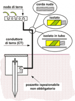
Here in Italy safety ground is not responsibility of the PU but every building has several direct connection to ground.
Attachments
I ordered a set of extra boards, with the idea to complete them with locally sourced components. It'll be fun to see how much difference I can hear between the different BoMs. Just finished the boards with the BoM sourced from ELFA. Measured the DC-offset, with input shorted to ground, at -5 and -2 mV.
Attachments
Dario,
Yes I have maybe 50 boards left. I bought large quantity. I figure that the more people build the more requests I will get for them.
You can still get them at Uriah Dailey
Uriah
Yes I have maybe 50 boards left. I bought large quantity. I figure that the more people build the more requests I will get for them.
You can still get them at Uriah Dailey
Uriah
So the same as a diode bridge connected like in ESP webpage, and with a 10ohm resistor parralelled?A plain wire will tie the public utility system directly to your "isolated and pure" signal ground.
A resistor is a current limited device. The circuit is never right if resistors are burning which would happen if certain conditions were raised in the amp.
A CL60 is a reactive component. It acts like a "slightly" resistive path ( 10 Ohms iir)during normal operation but an open in times of a catastrophic event not interfering with the normal design / function of the circuit / amp.
So you suggest to use the CL60, the ESP groud breaker could be good too?
btw can you elaborate on the pu polluted source concept?
Here in Italy safety ground is not responsibility of the PU but every building has several direct connection to ground.
I have never used the ground loop breaker so I can not comment on it's sonic contributions if any.
In the US we also have the premise grounded at the entrance of the service utilities. However refrigerators, washing machines and all sorts of other devices add garbage on the house ground. Also the incoming AC can have all sorts of nasty stuff (referenced to audio equipment not house hold appliances) on it depending on the grid you are connected to.
Older engineers used the "clean" ground, "dirty" ground model to keep the signal ground as isolated from the chassis or dirty ground as possible.
So the same as a diode bridge connected like in ESP webpage, and with a 10ohm resistor parralelled?
Please restate the question. I don't understand what you are asking.
- Status
- This old topic is closed. If you want to reopen this topic, contact a moderator using the "Report Post" button.
- Home
- Amplifiers
- Chip Amps
- MyRefC build guide