From past posts I would also suspect the LM318. If you compare both channels and everything is the exact same, as well as making sure there is no short between the sink and the tab of LM3886........... then I would feel rather safe swapping the LM318 you know to be good into the bad channel. Now, maybe you will fry it but on the other hand its a rather inexpensive part.
Uriah
Uriah
Hey, I have been burnin in these two boards for about 5 days, turned on all day and night. Sometimes with music, sometimes not. I have around 6-7mv of DC offset on each channel.
They sound really nice. I cannot exactly compare because I have just changed my speaker system too at the same time. I have a pair of brand new B&W CM5. The whole system is burnin in, so I will wait another week to get used to it's sound. Then, I will make the tantalum resistor change and report my listening results.
But I advice you that I am not golden ears guy, I just like listening to music and building stuff. I will make my best efforts to discern any audible difference.
Regards,
Regi
I have put two kits (one stereo) together.
I have made nice replaceable resistor dip-pin based sockets.
(I will post pictures later
One channel the relay clicks on. The other does not.
Re-checked all solder joints, nothing seems wrong.
Can someone give me a clue how to start trouble shooting? I don't want to blow the nice parts!!!
Michiel
I agree with what the others have said. The first thing I do is double check the polarity of the electrolitcs and the diodes and make sure the IC is in the socket the correct way. Then double check the heatsinks (chip and resister) to make sure they are not shorting - you should be able to do this with a multi-meter. Next start measuring voltages in the circuit. I would start with the power supply area of the board and next measure power rails at both ICs. If all of this seems good you can just start checking voltages across other components in the circuit and compare with the working board.
Hi Guys
Another RevC dual mono is born. I finally finished things yesterday, got 2 mv and 0.5 mv DC offset, not bad. Hooked it up using an old Marantz 1060 as a preamp, sounds very clean and smooth. Now I need let is burn in a few days and will use a SKA pre with a LDR pot to compare it to my old original Twisted Pear RevC. A fun project, thanks again for your efforts Uriah. Some pics below
PJN
Attachments
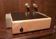
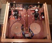
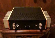
Nice build PJN, I like the wooden finish and the wood supporters for the transformers.
Good news: I have just finished assembling the LDR volume control that Uriah offered with the kit. After measuring and balancing both series and shunt LDR's with the trimpots, I took some more measurements and hooked it up to MyRef_C with ultimate BOM. It sounds very good, I like it.
I will connect it to my DCB1 buffer and see what improvements could I get. But at a first glance, it tracks smoothly without big jumps in sound changes. Max vol and min vol impedance measurements are right. Depending on volume position, the minimum impedance of input to ground I get is 7.8K and the maximum is 10.8. Well right between the expected results and the ones supported by the DCB1.
Regards,
Regi
Thanks for all the advice.
Little update
Problem switched from one channel to the other.
I did not insulate/isolate the resistor-heatsink.
Did not see/measure any contact.
I am working on that this evening.
Mechanical problems are more time consuming then electrical ones.
With the big caps it hard to screw the chips to the heath sink and back of and back on to get access to the bottom.http://www.diyaudio.com/forums/imag...iyaudio.com/forums/images/smilies/biggrin.gif
When put back together I will either listen or measure.
Michiel
I hope to come with some sonic feedback before upcoming holiday coming weekend.
K
Little update
Problem switched from one channel to the other.
I did not insulate/isolate the resistor-heatsink.
Did not see/measure any contact.
I am working on that this evening.
Mechanical problems are more time consuming then electrical ones.
With the big caps it hard to screw the chips to the heath
sink and back of and back on to get access to the bottom.http://www.diyaudio.com/forums/imag...iyaudio.com/forums/images/smilies/biggrin.gif
When put back together I will either listen or measure.
Michiel
I hope to come with some sonic feedback before upcoming holiday coming weekend.
K
I did not insulate/isolate the resistor-heatsink.
With the big caps it hard to screw the chips to the heath
Michiel,
Only sink to concern yourself with is the LM3886 sink. Yes its a pain with the caps in there. I ended up using a bolt with a phillips head. I hold the nut with needle nose pliers on the LM3886 side and screw it in with the screwdriver from the other side.
Looks like your LM318 is dead. So I imagine the other channel turned ON correctly?
Regi, Glad to hear you enjoy LDRs. They are incredible to me. Completely obsessed with them.
Uriah
Some people say that the big caps bring you the problem of not being able to properly screw the LM3886. With a medium-small screwdriver I could pass it between the two big capacitors and tightly attach the heatsink to the chip.Thanks for all the advice.
Little update
Problem switched from one channel to the other.
I did not insulate/isolate the resistor-heatsink.
Did not see/measure any contact.
I am working on that this evening.
Mechanical problems are more time consuming then electrical ones.
With the big caps it hard to screw the chips to the heath
When put back together I will either listen or measure.
Michiel
I hope to come with some sonic feedback before upcoming holiday coming weekend.
K
I don't know what is people using, but a 3-4mm diameter skrewdriver pass fine.
Regards,
Regi
Easy to solve the bolt issues. Use a bolt like thishttp://image.made-in-china.com/2f0j00DhatzOfPjQME/Hex-Socket-Bolt-Cup-Screw-JK-BT004-.jpg and a driver like this http://rocky.digikey.com/weblib/Wiha/Web%20Photos/mfg351%20series.jpg.
Easy.
Easy.
or use an overlong bolt with a nut turned all the way to the head. Insert the bolt through the chipamp clamping hole until it bottoms in the heatsink tapped hole and then use a spanner to turn the nut back down until it clamps the chip to the heatsink. Tighten till you reach specification.
I use an M3 socket cap screw, flat washer and nyloc nut. All stainless steel. I tighten the screw head using a suitable hex-read bit from my screwdriver set, and holding that bit in place with a spanner. I tighten the nyloc with a ratchet socket. Easy enough, as the screw passes through the current heatsink (which is quite thin). With my big sinks, I'll either use the bit and spanner technique, or drill right through the sink and counter drill from the back side with a hole big enough to fit my socket. To be honest, this is probably not really necessary, as the fins are quite widely spaced on the big sinks.
How do I do that?
Thanks
Just slowly tighten until you start to feel some resistance - that's the chip being pushed against the sink and the bolt starting to try and compress the chip. Maybe go another quarter turn and that's enough.
It's not a load bearing joint so it doesn't have to be mega, mega tight, just enough to hold the chip against the sink. It needs about as much pressure as you'd use to bolt the boards to their standoffs - i.e, not much.
I use m3 socket heads as well.
Yes, it's not something to worry about. Sure you will break either the nut or the bolt before you crack the IC. I just tight it until it makes some serious resistance, but not too much. Then I stopJust slowly tighten until you start to feel some resistance - that's the chip being pushed against the sink and the bolt starting to try and compress the chip. Maybe go another quarter turn and that's enough.
It's not a load bearing joint so it doesn't have to be mega, mega tight, just enough to hold the chip against the sink. It needs about as much pressure as you'd use to bolt the boards to their standoffs - i.e, not much.
I use m3 socket heads as well.
I received by kits a while ago, beautifully packed. Finally had the time to start building.
Has anyone used the supplied terminal pins for the power and output connections? I haven't been able to solder (.8 Sn, .38 Pv, .02 Cu) them, no matter how much flux I use. I've also tried scraping the surface with a knife to remove oxide.
(This has probably been brought up in previous build threads, but I don't know what the terminal pins are called in English, thus I've been unable to find anything.)
- Status
- This old topic is closed. If you want to reopen this topic, contact a moderator using the "Report Post" button.
- Home
- Amplifiers
- Chip Amps
- MyRefC build guide