I thought along those lines to Bob so switched things on again this morning; no joy same as last night.I don't understand why I am getting 31v at R14.When swiched of the voltage at R14 drops slowly to 21v before the relay clicks on/off.Beginning to wonder if I did'nt accidentally catch something when checking C102/202 although they still give +-14.5v.
Don't know if it will help Marra, but as I mentioned everything on my liquid cooled build worked except one LED. I could see no visible break in the solder in that area with a magnifying glass. I reheated both ends of R14 and nothing changed. Then I put a small amount of solder on the top of the PCB at the lead closest to the edge of the board and the LED works correctly. I don't know if the via was defective or damaged, but I did notice those are two of the smallest pads on the board.
Attachments
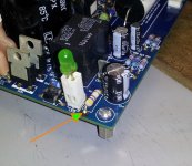
Thanks for the tip Bob.I noticed that the other end of R14 the solder had wicked up via the vias? but not at the edge of the pcb's so actually did that this morning.Unfortunately to no avail.I'm still confused as to the reason for there being 31V at R14 on that board whereas the other has 22V.Is it because the relay coil is not drawing any power?
Hi,
Today I tried to change the orientation of 1 ohm resistor. But I think I blown one of the resistor. No audio coming from one board. I dont have access to get only one resistor from Mouser or other online shops. Is there any alternative suggested? Or if possible to anyone to sell this resistor? Please help.
Thanks
Badri
I presume the two +24V are connected together !
Is R12 C14 ONLY supplying the relay circuit?
Measure the current through R14.
Measure the currents in the other resistors of the relay circuit.
You should find that all the currents add up.
Now compare the working version currents ot the non working version currents.
Is the output of the chipamp pulling the relay open?
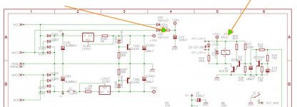
Why is the schematic supplying 31V to the relay circuit? Does a 24V relay need that much overdrive to pull in quickly?
Does the slow build up of charge (~1.2V) across C16 via current fed from 220k allow a fast trip of the relay? Or will the relay coil current increase until the solenoid thinks it's time to pull over and then the supply rail gets a big glitch and the charge on C16 drops and the relay releases. A stupid design. All three modified versions of my MyRef worked first time and every time Even though a reply to my post suggested I was daft to even contemplate changing the schematic. MyRef was a terrible implementation. This one is just as bad.
Is R12 C14 ONLY supplying the relay circuit?
Measure the current through R14.
Measure the currents in the other resistors of the relay circuit.
You should find that all the currents add up.
Now compare the working version currents ot the non working version currents.
Is the output of the chipamp pulling the relay open?
Why is the schematic supplying 31V to the relay circuit? Does a 24V relay need that much overdrive to pull in quickly?
Does the slow build up of charge (~1.2V) across C16 via current fed from 220k allow a fast trip of the relay? Or will the relay coil current increase until the solenoid thinks it's time to pull over and then the supply rail gets a big glitch and the charge on C16 drops and the relay releases. A stupid design. All three modified versions of my MyRef worked first time and every time Even though a reply to my post suggested I was daft to even contemplate changing the schematic. MyRef was a terrible implementation. This one is just as bad.
Last edited:
Why is the schematic supplying 31V to the relay circuit? Does a 24V relay need that much overdrive to pull in quickly?
Andrew, Maybe I'm reading your comment here incorrectly, bit I can't see 31V on the schematic.
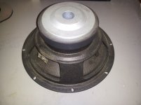
As long as there is no power connected to the bad amp that should work for testing. If you have a junk speaker (can even be a bare driver) of any kind or size, I would connect it to the non-working amp as a test also. What you hear might add some insight into the problem. I use a battery powered Walkman with a mini plug to RCA "Y" for these kinds of tests.
Attachments
Last edited:
 No need to put your other valuable equipment in jeopardy till problems are corrected.
But I think I blown one of the resistor. No audio coming from one board. I dont have access to get only one resistor from Mouser or other online shops. Is there any alternative suggested?
Measure that resistors with a multimeter...are you sure it's blown?
Sure, any carbon film will be fine (not as good as SPRs though)
- Status
- This old topic is closed. If you want to reopen this topic, contact a moderator using the "Report Post" button.
- Home
- Amplifiers
- Chip Amps
- My_Ref Fremen Edition RC - Build thread