LM3886T
Not for the MyRef projects, but if anyone wants some of the LM3886T non-isolated parts, I have 8 I would sell at a good price, still in their Digikey package. They were intended for a project which I won't do, now that I am building FE's.
Just to double check - did anyone buy the non-insulated LM3886? I don't know if they are even available new anymore, but could have been purchased on eBay. Those need an insulator. That is what is shown in the photo on post #29.
Not for the MyRef projects, but if anyone wants some of the LM3886T non-isolated parts, I have 8 I would sell at a good price, still in their Digikey package. They were intended for a project which I won't do, now that I am building FE's.
I would welcome the opinions of others, but I suspect the non-insulated chips could be used with the FE as long as the proper wafer is added. Aren't they functionally equivalent?
This is from the data sheet -
Proper mounting of the IC is required to minimize the thermal
drop between the package and the heat sink. The heat sink
must also have enough metal under the package to conduct
heat from the center of the package bottom to the fins
without excessive temperature drop.
A thermal grease such as Wakefield type 120 or Thermalloy
Thermacote should be used when mounting the package to
the heat sink. Without this compound, thermal resistance will
be no better than 0.5°C/W, and probably much worse. With
the compound, thermal resistance will be 0.2°C/W or less,
assuming under 0.005 inch combined flatness runout for the
package and heat sink. Proper torquing of the mounting
bolts is important and can be determined from heat sink
manufacturer’s specification sheets.
Should it be necessary to isolate V− from the heat sink, an
insulating washer is required. Hard washers like beryluum
oxide, anodized aluminum and mica require the use of thermal
compound on both faces. Two-mil mica washers are
most common, giving about 0.4°C/W interface resistance
with the compound.
Silicone-rubber washers are also available. A 0.5°C/W thermal
resistance is claimed without thermal compound. Experience
has shown that these rubber washers deteriorate and
must be replaced should the IC be dismounted.
The first two I bought are non-insulated and were never installed because they were used chips sold as new on eBay. Someday I will build a simple rig to test them, as well as some that were removed from other projects.
Errata Corrige
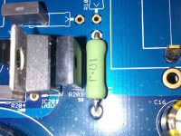
Sorry Guys but this part of the tutorial is WRONG.
The correct R11 orientation is this one:

The markings must go in the same direction of the arrow like all other components.
Only on capacitors I've reoriented silk screen text, not on resistors.

KOA SPR orientation, note that the marking on board have same orientation of the one on resistor.
Sorry Guys but this part of the tutorial is WRONG.
The correct R11 orientation is this one:
The markings must go in the same direction of the arrow like all other components.
Only on capacitors I've reoriented silk screen text, not on resistors.
Attachments
I would welcome the opinions of others, but I suspect the non-insulated chips could be used with the FE as long as the proper wafer is added. Aren't they functionally equivalent?
Absolutely LM3886T can be used.
The only difference is that you will need an insulator between it and the heatsink.
Dario, you and I are in a unique position as the only people who have completed the beta build. Some (I hope) may still finish populating those boards in the future. There will most likely be a final version developed from the experiences and suggestions of the RC builders.
As a point of reference and delineation, could you list the most significant changes that exist between the beta and the RC. One could go back through the posts for the information, but a concise description in one place, at this point, IMO, would be useful and add some clarity to the steps in the FE development. Not looking for great detail or in depth subjective evaluation here, just a list as a point of departure.
As a point of reference and delineation, could you list the most significant changes that exist between the beta and the RC. One could go back through the posts for the information, but a concise description in one place, at this point, IMO, would be useful and add some clarity to the steps in the FE development. Not looking for great detail or in depth subjective evaluation here, just a list as a point of departure.
Last edited:
As a point of reference and delineation, could you list the most significant changes that exist between the beta and the RC.
Hi Bob,
Beta and RC boards are pretty similar the differences are:
- RC boards are bigger
- C101, C201 can accept 35mm caps in RC boards
- R7, R12 are TH in beta and SMD in RC
- C34 is TH in beta, SMD in RC
- R39, R43 format changed from 1206 to 0805
- C13 is larger to accomodate Audyn True Copper
- R13, R104, R204 now can accomodate both 0309 and MK132 resistors
- Negative regulator in RC now uses LM317 instead of LM337
- Some layout changes
- The groundplane under DC protection has been slotted for better rejection
- C9/R10 on RC boards can be placed in two alternate configs.
Dario
Sorry Guys but this part of the tutorial is WRONG.
The correct R11 orientation is this one:
The markings must go in the same direction of the arrow like all other components.
Only on capacitors I've reoriented silk screen text, not on resistors.
Why resistor has orientation?
Why resistor has orientation?
At functional level there's no difference, obviously, and the amp perform at full potential in either direction.
But at subjective level there's a tiny sound difference (usually in one direction you can hear a fuller and sweeter sound, in the other a more fatiguing sound, a bit harsher with (too much) tighter bass and bigger soundstage).
If you don't trust it's real, simply ignore it.
")
I suggest builders, though, to follow direction indications on boards to achieve full subjective performance.
Last edited:
The first channel is running ;-)
Amazing results for a chip based amplifier, I kept telling Dario that this is not possible for a chip amplifier to perform nicely because I did not like bare LM3886... Overall, it is much better than bare LM3886 IMHO.
Compared to bare LM3886, the bass is tighter and the highs are distinguishable, smooth and clean, not harsh, you will like them. You can distinguish the instruments you hear while playing classics, and it can happily play low end without problems. Voices are simply charming
I listened to many colors, the amplifier excelled in all, very good indeed.
Thanks to Dario who made it possible, of course!
More photos tomorrow, I like to take photos under the sun, they will be more detailed tomorrow.
Omar
Attachments
The first channel is running ;-)
Good job, Omar!
Amazing results for a chip based amplifier, I kept telling Dario that this is not possible for a chip amplifier to perform nicely because I did not like bare LM3886... Overall, it is much better than bare LM3886 IMHO.
You bet!
Thanks to Dario who made it possible, of course!
You're welcome
More photos tomorrow, I like to take photos under the sun, they will be more detailed tomorrow.
We'll wait fot them
Thanks Bob.
BTW, Dario suggested that I might want to remove C102 and C202, I removed them already. I am about to finish the second channel. Tomorrow will take more photos and play both channels.
~~It is worth mentioning that excellent solder is essential~~
THIS AMP MADE MY DAY
BTW, Dario suggested that I might want to remove C102 and C202, I removed them already. I am about to finish the second channel. Tomorrow will take more photos and play both channels.
~~It is worth mentioning that excellent solder is essential~~
THIS AMP MADE MY DAY
Last edited:
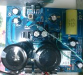
Second channel photos
Where are the rest of the builders
An externally hosted image should be here but it was not working when we last tested it.
An externally hosted image should be here but it was not working when we last tested it.
Where are the rest of the builders
Last edited:
Hi Metal
Which parts list did you use - the recommended BOM or the BOM on a budget?
Thanks
Which parts list did you use - the recommended BOM or the BOM on a budget?
Thanks
The first channel is running ;-)
Amazing results for a chip based amplifier, I kept telling Dario that this is not possible for a chip amplifier to perform nicely because I did not like bare LM3886... Overall, it is much better than bare LM3886 IMHO.
Compared to bare LM3886, the bass is tighter and the highs are distinguishable, smooth and clean, not harsh, you will like them. You can distinguish the instruments you hear while playing classics, and it can happily play low end without problems. Voices are simply charming
I listened to many colors, the amplifier excelled in all, very good indeed.
Thanks to Dario who made it possible, of course!
More photos tomorrow, I like to take photos under the sun, they will be more detailed tomorrow.
Omar
Actually a mix, all resistors are from recommended list, except for the 0R47 output resistor.
And R104, R204 are KOAs from On a budget BOM instead of MK132s
And R104, R204 are KOAs from On a budget BOM instead of MK132s
Yes, I forgot to mention them
You got my list
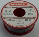
That is beautiful soldering. Can you tell us what brand and size solder you used?
SOLDEX 5 cored 60/40 0.75mm
www.soldex.com.tr / Ya?mur Metal Elektronik ?malat San. ve Tic. Ltd. ?ti.
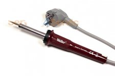
I am using weller SPI 27.
Attachments
 Thanks.
- Status
- This old topic is closed. If you want to reopen this topic, contact a moderator using the "Report Post" button.
- Home
- Amplifiers
- Chip Amps
- My_Ref Fremen Edition RC - Build thread