Old Boards + jfet opamp Update
As a reminder, I have built two v1.2 boards with evo A + ADA4627 and had DC offset issues with one board. If the DC coupling cap (C13) is used, a minimum of 1VDC offset is present. After a lot of help from George, I couldn't find the cause and was only able to play the amp DC coupled (no C13) at about 70 mVDC offset.
To try to solve this issue and be able to run with C13, I built a V1.1 board using all new components except the ADA4627, R3, and the reservoir caps. Unfortunately, this has even worse DC offset with 3 to 5 VDC with input shorted, C9 shorted, and C13 in place. I tried many possible variations, including installing C9 and the DC offset remains.
By the way, this board has excellent power supply voltages and no oscillation, even without a 5 pF compensation cap.
I decided that the issue has to be either some unknown design issue or one of the components brought over from the v1.2 board. My only other jfet opamp that I have is the OPA627, so I replaced the ADA4627 with the 627. As George has noted, the 627 is a tricky amp that can oscillate easily. On first attempt, without compensation cap, I had 7 VAC and 1.5VDC offset. Sounds like oscillation to me. I added the compensation cap and, with C9 still installed, the output was perfect (DC offset 1.2 mV, AC at 0.8 mV).
First conclusion is that I must have damaged the 4627 at some point because it is clearly worse than the 627 for the same configuration.
My most recent combination uses the 627 and replaces C9 with a jumper. Unfortunately, DC offset goes back up to 1.5 VDC. At least there is no oscillation.
I can't really draw any other conclusion other than there seems to be an issue with the old boards that is not there with the new boards and makes the new jfet opamps more difficult to use with old boards. Given my experience with 2 out of 3 boards being unable to work except as DC coupled, I would recommend others avoid old boards or go forward with eyes wide open.
Going forward, I will try building two boards with OPA627 and C9. If both are stable, I will do some listening in that configuration. If not, these boards are going back to the LM318. After that experience, I will have to decide how many new boards to order. ;-)
Jac
Going forward, I will try building two boards with OPA627 and C9. If both are stable, I will do some listening in that configuration. If not, these boards are going back to the LM318. After that experience, I will have to decide how many new boards to order. ;-)
Jac
Cool. There are 9 sets registered, one more and the GB starts.
I could order 2 sets instead of one because I want to A/B two different OPA (ADA4637 and OPA827).
Not feeling like trying 827? 😉
And it would be nice to be able to organize an audition, Guido!
Ciao, George
You need to come to Milan 🙂
bottom audio location is so far that most people from north and south don't go 🙁 I read on italian forum that you brought your evo with latest mods and that it was a success 😉
Cool. There are 9 sets registered, one more and the GB starts.
I could order 2 sets instead of one because I want to A/B two different OPA (ADA4637 and OPA827).
I do want to have at least 2 pair for comparison, but I don't mind swapping out parts. I have lots of practice. The number I need will be thinking about overall projects.
Not feeling like trying 827? 😉
Of course. I originally ordered the 4627 because it was George's favorite. I actually had a pair of 627 as they have been my favorite up until now. Honestly, from the spec sheets, I think all three 4627, 827, and 627 are very close in the areas that are key to me. But the old 627 is pricey, so I'm hoping one of the other two will match or exceed my 627 experience.
Jac
I do want to have at least 2 pair for comparison, but I don't mind swapping out parts. I have lots of practice.
I dont 🙁
I originally ordered the 4627 because it was George's favorite. I actually had a pair of 627 as they have been my favorite up until now. Honestly, from the spec sheets, I think all three 4627, 827, and 627 are very close in the areas that are key to me. But the old 627 is pricey, so I'm hoping one of the other two will match or exceed my 627 experience.
Jac
Add the 4637 to that list. On paper it looks better than it's twin (A grade even).
Thanks guys.
George, sincerely I would have kept it out of this forum but at the same time people didn't understand why I was so 'detached', why I didn't try your great work on alternate opamps.
In fact I've bought all the necessary but my mood it's not up to the task...and time less and less.
BTW, as an hypothesis, I've also explored other ways to achieve the same result keeping the LM318:
This approach it's not plug'n'play like yours and will need pretty different new boards (much more space is needed), and in this case a second HCPcould be added. 🙂
Also a competent engineer will be needed to correctly size the circuit and compensate it, George do you know someone? 😉
I would like this approach best since it would maintain the LM318 loved by Penasa, improve it's performances as Musical Fidelity did in latest versions of the A/P-x70 amplifiers and the resulting amp would have the double pump option... but possibly years of work will be needed.
An afterthought: in this post at #3843, this 'trick' with the swapped out input pair -- had been tested and suggested for transistors.
I stated that it could work even in the configuration shown by Dario.
I feel to make a step back, and say: should be tried.
The problem is: FET's need a much higher bias to provide some gain, and even in that case it is much less gain that with the original input pair, or with the substitute input configurations mentioned.
The problem with higher bias is that still the original chip's internal upper branch current mirrors are used; those are the ones which must handle this higher current flowing, and it's not given at all that they are tuned OK for it.
That is, usually 2mA for the input pair - in a chip - is a lot; on the other hand at **1mA 'only' input FET's are not at their maximum capability.. (**each FET sees only the half of the bias current)
(2mA the bias that Dario had configured; 200uA the bias in the article; 300uA the bias in the A270/370...)
Ciao, George
Last edited:
Speaker Protection from DC
My recent experience with DC offset has reminded me that the speaker protection circuit requires a fair bit of DC to open the relay. I found the relay typically opening at about +5VDC with my DC offset boards. In my opinion, this is on the high side and I would like the speaker to be protected from about +/-2 VDC. What do you guys think is an appropriate level?
My recent experience with DC offset has reminded me that the speaker protection circuit requires a fair bit of DC to open the relay. I found the relay typically opening at about +5VDC with my DC offset boards. In my opinion, this is on the high side and I would like the speaker to be protected from about +/-2 VDC. What do you guys think is an appropriate level?
In my opinion, this is on the high side and I would like the speaker to be protected from about +/-2 VDC. What do you guys think is an appropriate level?
I think 1V.
Jac,
I think it was a play of balance, from Mauro.
Probably the dynamic behaviour with music contents was the determining factor.
You could experiment: replace the 10k component in each branch divider ( 75k/ 10k) . 22k and finally 33k.
33k would give a static 2,2V limit.
You could decide if it is still stable at high level dynamic music peaks..
Ciao, George
Jac,
I think it was a play of balance, from Mauro.
Probably the dynamic behaviour with music contents was the determining factor.
You could experiment: replace the 10k component in each branch divider ( 75k/ 10k) . 22k and finally 33k.
33k would give a static 2,2V limit.
You could decide if it is still stable at high level dynamic music peaks..
Ciao, George
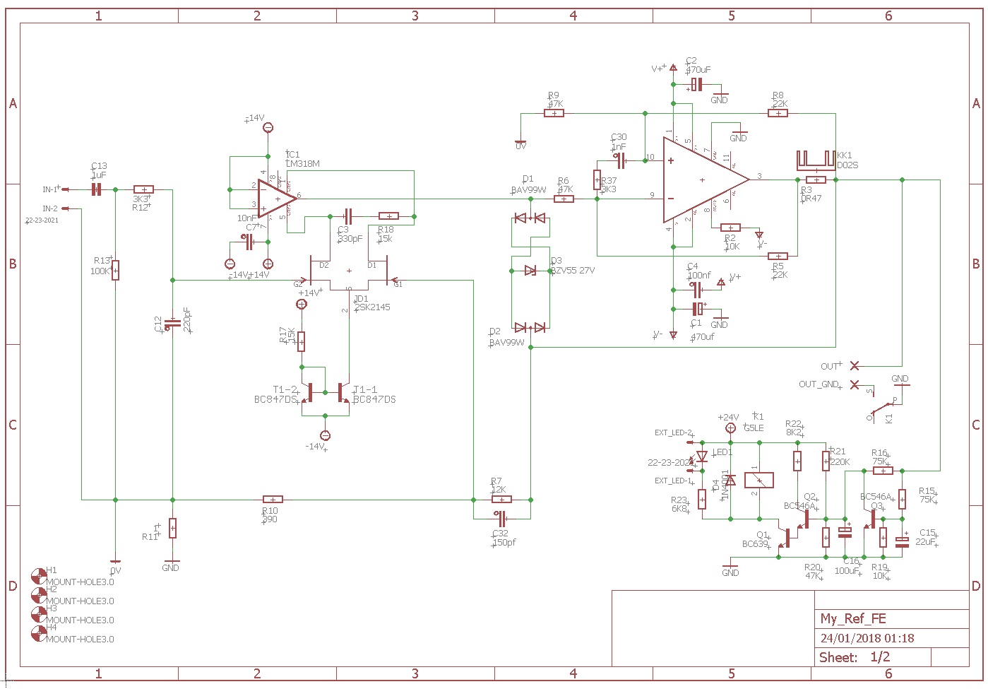
Actually, I have played with this (see post 451, page 46) and have been using a small circuit modification since 2013 (test boards) and for about a year on 2 more pair, all without problems. What bugs me the most is that a negative DC voltage isn't actively switched. Well, sort of.
The circuit diagram below shows what I have been using. As shown, it opens the relay at +1.5/-1.7VDC, but of course, this can be easily and independently changed. Note that I used a 2N4403 as a PNP in the Q4 position, but most any PNP could be used.
I would like to see some change to the BOM or the circuit to improve this.
Jac
Attachments


Last edited:
An afterthought: in this post at #3843, this 'trick' with the swapped out input pair -- had been tested and suggested for transistors.
I stated that it could work even in the configuration shown by Dario.
I feel to make a step back, and say: should be tried.
Great! I'm happy this circuit is starting to intrigue you 🙂
The problem is: FET's need a much higher bias to provide some gain, and even in that case it is much less gain that with the original input pair, or with the substitute input configurations mentioned.
The problem with higher bias is that still the original chip's internal upper branch current mirrors are used; those are the ones which must handle this higher current flowing, and it's not given at all that they are tuned OK for it.
That is, usually 2mA for the input pair - in a chip - is a lot; on the other hand at **1mA 'only' input FET's are not at their maximum capability.. (**each FET sees only the half of the bias current)
(2mA the bias that Dario had configured; 200uA the bias in the article; 300uA the bias in the A270/370...)
It's for this exact reason that I need your help 😉
Values on schematic, though, are just placeholders... never made any calculation/sizing on it...
Nevertheless you're perfectly right, the needed bias for a jfet LTP would be around 2-3mA as we can see in this other example:
An externally hosted image should be here but it was not working when we last tested it.
Ref: https://www.edn.com/Home/PrintView?contentItemId=4419861
I didn't consider that the LM318 internal CCS would have been still in function and possibly overloaded... this could be a problem that with BJTs as used in AN222 is not relevant.
OT Solder
For years now, I have been using a very old Weller soldering iron that is thermostatically controlled, but can't reach soldering tip temperatures for lead-free solder. I have just ordered a new soldering iron that will allow lead-free soldering. I was wondering, what are you guys are using for solder?
I have been reading online and find some people prefer RA (ROL0) or RMA (ROL1) flux for hand soldering, especially over "no clean" flux. Any experience?
I also find recommendations for high silver content, at least 3.5%, for better wetting and flow. I also see people trying tin-antimony solders. Any thoughts?
In the end, I have lots of tin-lead solder, so I may just crank up the fan and stay with that.
Thanks in advance.
Jac
Dario is using Cardas eutectic solder. I still use solder with lead, that is easier to melt and EU regulations don't apply for DIY 😀
Dario is using Cardas eutectic solder. I still use solder with lead, that is easier to melt and EU regulations don't apply for DIY 😀
As I understand it, Cardas is still using lead, but adds silver and copper is small amounts. It appears they are using an activated rosin core flux or RA.
I'm currently using Kester 63/37 #66/44 core. That's a "eutectic" tin-lead solder with an RA core.
Hi Jac,I have just ordered a new soldering iron that will allow lead-free soldering. I was wondering, what are you guys are using for solder?
regarding ROHS solder I use only eutectic alloys, RS Components 756-8884 for SMD hand soldering and general soldering work and Oyaide SS-47 for critical audio through hole soldering.
Both are easy to work with and sound good.
Oyaide flux smells like something coming straight from hell, though.
I expect WBT Lead-Free solder to be very good too.
Where did you get this info? Not true.Dario is using Cardas eutectic solder.
Data for RS solder alloy:
The alloy used in this solder wire c
ontains 96.5% tin, 3.0% silver and
0.5% copper and conforms to J-STD 006
Melting point 217 - 219.C
3.3% flux content.
Flux classification per J-STD 004 is ROL0 leaving a highly reliable post
soldering residue.
The alloy used in this solder wire c
ontains 96.5% tin, 3.0% silver and
0.5% copper and conforms to J-STD 006
Melting point 217 - 219.C
3.3% flux content.
Flux classification per J-STD 004 is ROL0 leaving a highly reliable post
soldering residue.
Hi Dario,
Thanks Dario. The RS looks very similar to other brands sold in the US. I see that it is "no-clean" flux. I've read that no clean is harder to clean off, if you want to. How is your experience?
I have some Chip Quik tin-lead that uses no clean flux and I have a hard time getting a small amount to melt on the iron for SMD soldering. It likes to form a drop on the end of the wire and then fall on the bench. I have wondered if this is due to the flux.
I have heard that the Oyaide smells awful.
Thanks,
Jac
Attachments

Last edited:
I use the Cardas solder for TH. It is excellent. Melts pretty easily, flows nicely, makes a smooth, shiny joint. Doesn't smell like perfume, but it's not awful. Flux is a bit hard to clean.
People are always confusing Dario with me, but Dario is the handsome one. 😉
Peace,
Tom E
People are always confusing Dario with me, but Dario is the handsome one. 😉
Peace,
Tom E
I use the Cardas solder for TH. It is excellent. Melts pretty easily, flows nicely, makes a smooth, shiny joint.
People are always confusing Dario with me, but Dario is the handsome one. 😉
Peace,
Tom E
Thanks Tom.
And Dario is not only handsome, but I'm sure the Salsa dancing sweeps the ladies off their feet.
PS Nobody here knows what I look like. Unless they think I look like an orange opamp with two tubes for ears.;-)
- Home
- Amplifiers
- Chip Amps
- My_Ref Fremen Edition - Build thread and tutorial