I don't see any significant difference between 100V/usec or 70V/usec slew rate (lm318) so if it works with lm318 then similar slewing device should not be more difficult.
Guilty of not having checked the lm318 datasheet.
So it works rather on the contrary: moderate to high slew rate is not a problem; low slew rate is..
Then it should be easier/better than 4627 which is much slower, while keeping the same ultralow distortion and PSRR.
Condolences for your loss.
Dario, my condolences too. You kept very silent about it (normal..)
Thanks guys.
George, sincerely I would have kept it out of this forum but at the same time people didn't understand why I was so 'detached', why I didn't try your great work on alternate opamps.
In fact I've bought all the necessary but my mood it's not up to the task...and time less and less.
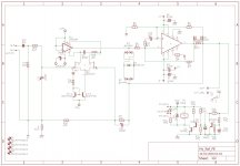
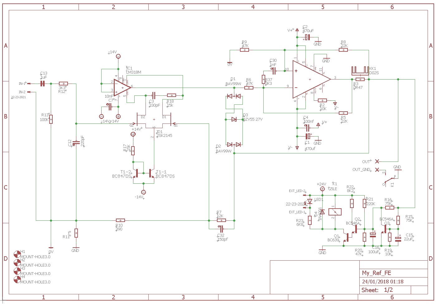
BTW, as an hypothesis, I've also explored other ways to achieve the same result keeping the LM318:
This approach it's not plug'n'play like yours and will need pretty different new boards (much more space is needed), and in this case a second HCPcould be added.
")
Also a competent engineer will be needed to correctly size the circuit and compensate it, George do you know someone?
I would like this approach best since it would maintain the LM318 loved by Penasa, improve it's performances as Musical Fidelity did in latest versions of the A/P-x70 amplifiers and the resulting amp would have the double pump option... but possibly years of work will be needed.
Attachments
First power up
Hi everyone,
after the relay's click I started measuring the DC offset at Output tabs.
Respecting output tab polarity with the tips, the multimeter reads -7 mV (-5 mV shorted input) on both the boards.
Sorry for the newbie question: Is that right?
Thanks for this outstanding thread.
Hi everyone,
after the relay's click I started measuring the DC offset at Output tabs.
Respecting output tab polarity with the tips, the multimeter reads -7 mV (-5 mV shorted input) on both the boards.
Sorry for the newbie question: Is that right?
Thanks for this outstanding thread.
after the relay's click I started measuring the DC offset at Output tabs. Respecting output tab polarity with the tips, the multimeter reads -7 mV (-5 mV shorted input) on both the boards.
Is that right?
The polarity doesn't matter. Those numbers are fine. As a side note, they will probably get a little smaller after a while.
Jac
BTW, as an hypothesis, I've also explored other ways to achieve the same result keeping the LM318:
This approach it's not plug'n'play like yours and will need pretty different new boards (much more space is needed), and in this case a second HCPcould be added.
Also a competent engineer will be needed to correctly size the circuit and compensate it, George do you know someone?
Dario,
I am not circuit design expert (or even close), but there are a couple of things I noticed. I like the small cap size in the compensation circuit. One thing I worry about is the drift of both the mosfet and the BJT's over time and temperature. The Pass F4, for example, takes 20 or 30 minutes for the bias current to reach a stable target value. In that application, the mosfets are passing a lot of power and this case would be much less severe, but it may be something to think about.
I am curious about what someone with more experience would say about the circuit. I guess I don't completely understand why DC servos don't sound as good as no servo and how this might sound different. I am thinking this is zero target version of a Circlotron or something similar. The Circlotron actively controls the bias current so that it remains just in or just out of Class A. As the current demand grows larger, the bias current is adjusted so that most of the signal is Class A. This circuit seems to actively change to keep the DC offset very small. Or am I misunderstanding it?
Jac
I am not circuit design expert (or even close), but there are a couple of things I noticed.
Me too...
I like the small cap size in the compensation circuit. One thing I worry about is the drift of both the mosfet and the BJT's over time and temperature. The Pass F4, for example, takes 20 or 30 minutes for the bias current to reach a stable target value. In that application, the mosfets are passing a lot of power and this case would be much less severe, but it may be something to think about.
I don't know, it's one of the reason I've asked help on sizing...
I am curious about what someone with more experience would say about the circuit. I guess I don't completely understand why DC servos don't sound as good as no servo and how this might sound different. I am thinking this is zero target version of a Circlotron or something similar. The Circlotron actively controls the bias current so that it remains just in or just out of Class A. As the current demand grows larger, the bias current is adjusted so that most of the signal is Class A. This circuit seems to actively change to keep the DC offset very small. Or am I misunderstanding it?
This circuit has nothing to do with Servos...
The whole input stage of the LM318 is disabled and it is replaced (using pins 1 and 5) by the jfet LTP, biased using a current mirror and compensated by C3 and R18.
In practice it makes a jfet input opamp the LM318.
This has been done (using BJTs) by Musical Fidelity on later versions of A/P-270 and on some preamps
Last edited:
The whole input stage of the LM318 is disabled and it is replaced (using pins 1 and 5) by the jfet LTP, biased using a current mirror and compensated by C3 and R18.
In practice it makes a jfet input opamp the LM318.
This has been done (using BJTs) by Musical Fidelity on later versions of A/P-270 and on some preamps
OK. I see a little better what you are doing. If I understand it correctly, you are bringing the signal in at the compensation pins (1 and 5). I've never seen that done.
From the 318 datasheet, pins a and 5 are directly connected to the output of the input stage. With your input to pins 2 and 3 being equal, the output of the input stage should be zero. Your external jfet input stage has gain and so does the 318 input stage. When those two signal pairs are connected to each other, I don't know what would happen. Again, not being a circuit design guy, I worry that the jfet input stage is controlled by feedback, so it's gain would be 30 and the input stage about 100. I'm not sure what the output stage would see.
Honestly, I think it would be cleaner to either use a jfet voltage stage without an opamp or use a jfet opamp.
Jac
The whole input stage of the LM318 is disabled and it is replaced (using pins 1 and 5) by the jfet LTP, biased using a current mirror and compensated by C3 and R18.
In practice it makes a jfet input opamp the LM318.
This has been done (using BJTs) by Musical Fidelity on later versions of A/P-270 and on some preamps
TBH it is an overcomplication which isn't needed IF a jfet input opamp is used in place of LM318.
Please test that first (in the my_ref). If I can help somewhat with scope etc, just ask.
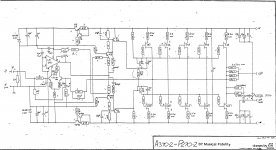
The replacing of the internal input stages of LM318 has been introduced by Carl T. Nelson in July1979 in the National Semiconductor AN-222 Super Matched Bipolar Transistor Pair Sets New Standard for Drift and Noise" obtaining straordinary results in distorsion and noise. In my opinion, this is a promising way to follow.

The replacing of the internal input stages of LM318 has been introduced by Carl T. Nelson in July1979 in the National Semiconductor AN-222 Super Matched Bipolar Transistor Pair Sets New Standard for Drift and Noise" obtaining straordinary results in distorsion and noise. In my opinion, this is a promising way to follow.
Fascinating! Very similar to Dario's proposal and exactly the same input method. I would have thought the two input stages would interact, but it seems it's OK.
One thought, Dario. I remember reading somewhere a comment from SY that using a constant current source rather than a resistor tail in a long tail pair is preferred and easy. In the Impasse pre that I built, he uses 2 DN2540 depletion mode mosfets and three resistors to provide a very robust constant current.
Jac
Thanks so much Jac, I've a lot of things to learn and this seems the right place to start.
Antonio
Hi Antonio,
Welcome to the fun. Based on the flag with your name, you are surrounded by smart people familiar with this project.
Jac
OK. I see a little better what you are doing. If I understand it correctly, you are bringing the signal in at the compensation pins (1 and 5). I've never seen that done.
(...)
Honestly, I think it would be cleaner to either use a jfet voltage stage without an opamp or use a jfet opamp.
Hi Jac,
as Andonio pointed out Musical Fidelity engineers didn't anything new but it works.
In general you're right but I like the idea on following Musical Fidelity (which inspired Penasa) path with these amps.
And, while on different circuit, I didn't find a JFET opamp that give me same emotions of the LM318.
TBH it is an overcomplication which isn't needed IF a jfet input opamp is used in place of LM318.
Please test that first (in the my_ref). If I can help somewhat with scope etc, just ask.
This FE 2.0 is a long term project, it will not see the light before one year of two.
In the meanwhile JFET opamps can be used and I will try them for sure.
The replacing of the internal input stages of LM318 has been introduced by Carl T. Nelson in July1979 in the National Semiconductor AN-222 Super Matched Bipolar Transistor Pair Sets New Standard for Drift and Noise" obtaining straordinary results in distorsion and noise. In my opinion, this is a promising way to follow. View attachment 673335
Thanks for the reference, I knew it existed but never managed to find it
One thought, Dario. I remember reading somewhere a comment from SY that using a constant current source rather than a resistor tail in a long tail pair is preferred and easy. In the Impasse pre that I built, he uses 2 DN2540 depletion mode mosfets and three resistors to provide a very robust constant current.
Jac, the circuit I have posted doesn't use a resistor tail in the LTP but a current mirror (that is a CCS).
Current mirrors are widely used in opamps design.
Attachments
While it would be going away from the chip/modular/simple elegance of the original implementation, I would think that a discrete op amp may give some gains while maintaining the overall tonal balance of the lm318.
It would be still be modular if one used an available discrete op amp I suppose.
It would be still be modular if one used an available discrete op amp I suppose.
IME the lm318 in this circuit is very much influenced by the characters of the components which the signal pass through, including the loudspeaker crossover. That is, I think the lm318 doesn’t have much of a character of its own. Listening to a my_ref with the industrial BOM, there is no tube-like character at all, to my ears.
A change of this magnitude would be better tested with an 8 ohm wideband speaker connected directly to the amp output with short thick cables.
Dario, I’m looking forward to the FE2
Btw, I’d like to buy or audition an Evo full. If someone not too far from Milan is interested, pm me.
A change of this magnitude would be better tested with an 8 ohm wideband speaker connected directly to the amp output with short thick cables.
Dario, I’m looking forward to the FE2
Btw, I’d like to buy or audition an Evo full. If someone not too far from Milan is interested, pm me.
Last edited:
Jac, the circuit I have posted doesn't use a resistor tail in the LTP but a current mirror (that is a CCS).
Current mirrors are widely used in opamps design.
You see Dario, you are a far more knowledgeable circuit designer than I am. I have been playing in the tube world a bit and I am used to seeing high voltage drop CCS that look quite different than the current mirror. But then tubes are very different animals.
At least we got some discussion of your proposal.
Jac
Dario,
I can only say that it had always been a joy to work with You. So you can count on me.
What regards your scheme:
Yes, I think it can be tried. I do not have an opinion how it would sound. Trying to be neutral and open, I mean. Technically speaking: it would definitely work. To Guido: it could work, because by tying the original inputs to the negative rail, the internal long tailed pair (and it's current source) are off. For this the new i put pair needs a new current source installed. The original current mirrors and all the rest of the chip are active.
Though: changing to fets we giving up on gm of the input pair. There will be much lower open loop gain left for correction. In the same time the original pole probably creeps upwards, the slew rate will depend on how is the input pair biased.
It will be hard to simulate this, given the lack of good models.. but the good old network analyzer could help..
Then: 1 and 5 are a high impedance point, and though the inputs are ~off, all the parasitics effects remain.. just guessing. Most probably a 'clean' design, like a modern opamp designed from new ground and with high quality technology.. like the OPA827, or 1641.. are capable of performing just better from the start.
Another point: in the present mods C9 can be eliminated because of the use of precision Fet opamps, with 70-100 uV offset.
I did not check the offset quality of that double fet used here, but would be surprised if it would have offsets below the 10's of mVs zone. That is 300mV in output.
So, not a bad idea - actually Linuxguru wasn't doing something similar before?
But needs work and testing. Also I would think that actually ready made discreet opamps could be an another option..
Compensation will be a rough ride, though!!
Ciao, George
Last edited:
- Home
- Amplifiers
- Chip Amps
- My_Ref Fremen Edition - Build thread and tutorial