Hi guys,
I'm just trying to understand your thinking. I get that adding the cap between pins 2 and 6 limits the upper bandwidth to filter out an oscillation. What resistance are you using to calculate the corner frequency with the 3.3 pF cap?
My first reaction was to use the output impedance of the opamp, but that doesn't work. The Gain-Bandwidth product gives us about 600 kHz at this gain. I would have thought it would take a bigger cap to limit the upper bandwidth to the 100 - 150 kHz level.
Still learning every day. Thanks in advance.
Jac
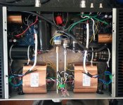
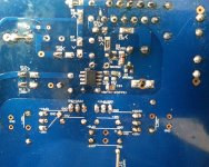
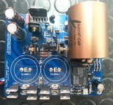
Photos would help a lot!
Here some pics of my build, i hope they can help!
At present i have no cap below 100pF, so a while will be needed before i can try the suggested 3,3pF cap mod...
Attachments
And Since I am asking Questions
I have been rereading Mauro's project my_ref and thinking about the circuit. One area I am interested in understanding better is the input filter. Mauro talks about R12 and C12 as a low pass filter to limit the upper bandwidth of the input.
George referred us to the OPA1622 opamp discussion, in particular where johnc124 was discussing issues with high input impedance for an opamp.
As I have been studying resistors, it is also clear that higher value resistors and higher voltage drop across resistors are negatives for noise.
R12 at 3.3k isn't terribly high, but it is in the signal path and noise introduced at the input will often be amplified. Also, having a lower input impedance is generally a good thing for opamp.
Has anyone considered changing R12/C12 from 3.3k/220pF to 330R/2.2nF, for example? I am probably missing something, but it seems like it shouldn't change the circuit performance other than a possible noise improvement.
Jac
Has anyone considered changing R12/C12 from 3.3k/220pF to 330R/2.2nF, for example? I am probably missing something, but it seems like it shouldn't change the circuit performance other than a possible noise improvement.
I've just been thinking about this too, but for slightly different reasons. Apart from noise reduction, this mod would equalize (roughly) the impedances seen by the inputs of the op-amp, and it's the inequality here that leads to large DC offsets with the LM318. So, doing this should lead to much lower DC offsets if someone fancied getting rid of C9 but didn't want to replace the LM318. The amp would need to be fed with a low impedance for this to work.
Hi guys,
I'm just trying to understand your thinking. I get that adding the cap between pins 2 and 6 limits the upper bandwidth to filter out an oscillation. What resistance are you using to calculate the corner frequency with the 3.3 pF cap?
My first reaction was to use the output impedance of the opamp, but that doesn't work. The Gain-Bandwidth product gives us about 600 kHz at this gain. I would have thought it would take a bigger cap to limit the upper bandwidth to the 100 - 150 kHz level.
Still learning every day. Thanks in advance.
Jac
I just did what George said - I had a minor instability when I first fitted the ADA4627. I'm still learning too!
Hi guys,
I'm just trying to understand your thinking. I get that adding the cap between pins 2 and 6 limits the upper bandwidth to filter out an oscillation. What resistance are you using to calculate the corner frequency with the 3.3 pF cap?
My first reaction was to use the output impedance of the opamp, but that doesn't work. The Gain-Bandwidth product gives us about 600 kHz at this gain. I would have thought it would take a bigger cap to limit the upper bandwidth to the 100 - 150 kHz level.
Still learning every day. Thanks in advance.
Jac
Jac, it's not the closed loop gain at wich we have to look at the GBW..
The opamp is seeing the comp cap applied to it's open-loop gain, inside the composite loop.
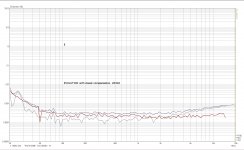
For illustrating the effect of this compensation cap, I have done a scan of the loop gain changing as this compensation cap is changed. What is shifting more importantly is the phase margin of the composit loop.
The scan had been done as illustration, with the OPA627 in the loop, +the LM3886 current pump. The load is 8ohm+4nF.
The 627 is similar in many ways to the 4627; the effect, the direction of change is the same in all cases.
Watch the phase margin values in a, b points, the Y value is the phase margin at 0dB loop gain cross level.
Ciao, George
Attachments
Then, for fun, I would like to point out that this compensation type, the small comp. capacitor directly across U1 inside the composit loop is / was invented naturally not by me.. I'm just using it with these new opamps, while we are staying outside of the Rev-C type compensation fields..")
Look who had used it principally in the pre-historic, ancient christian periods..)
http://www.diyaudio.com/forums/chip-amps/54571-audiophile-lm3886-approach-7.html#post671968
Ciao, George
Look who had used it principally in the pre-historic, ancient christian periods..
)http://www.diyaudio.com/forums/chip-amps/54571-audiophile-lm3886-approach-7.html#post671968
Ciao, George
At present i have no cap below 100pF, so a while will be needed before i can try the suggested 3,3pF cap mod...
Try it with 100pf as an experiment. It won't sound as good - you'll lose a lot of feedback and THD will go up - but at least you'll know if the problem is stability.
Has anyone considered changing R12/C12 from 3.3k/220pF to 330R/2.2nF, for example? I am probably missing something, but it seems like it shouldn't change the circuit performance other than a possible noise improvement.
Jac,
I don't want to be strong about it; what you sugest is definitely possible, but...
By raising the input filter cap value, and lowering R12, you are pointing to an ideal drive condition, with very low generator impedances. Now this can or can not be true. Modern Dac outputs directly applied to the amp would satisfy;
Any potentiometer would heavily disqualify; tube pre outputs (kohm range) would result in some khz total bandwith, I'm afraid..
But even soundcards, usually are having a couple of hundred ohms as output impedance.
So for this reason I see the 220pF filter cap as a more generally applicable, and usual solution..
Then, what Dan (Spartacus) mentiones is true: for offset equalization a lower input series resistance would be better; here I would point out that I had used my amp this way, with the original 3,3kohm in place -- the generated offset is not 'lethal', still in the managable range. though less is clearly better.
Ciao, George
I would add here a little more fun:
I happen to have a 'NOS' My-Evolution amplifier in my reach right now;
It is a single pump, classic configuration. What is more interesting for us here that the 'classic' Evo-compensation configuration happens to be quite coincident with the present standard-BOM FE compensation scheme.
Some time ago there were some questions about the technical differences between the FE standard compensation and the so-called Rev-A compensation scheme.
Many people now had just made this step, passing from the original compensation to the rev-A compensation.
So it might be interesting how these compare: an Evolution amp configured in the 'classic' way (FE standard BOM)
An Evolution amp configured according to the rev-A modifications; (one can expect a very similar result with the FE too
And finally I had measured again my usual, rev-A modified, full double current pump Evolution amp (with OPA827).
Here it is the classic EVO (~ with standard FE compensation)
Note the distortion floor; it's higher level reflects the lower loop gain as a result of this compensation (470k on LM318)
THe low frequency rise is the consequence of the DC-servo loop entering into action; (principally it's valid only for the EVO amp)
The relatively flat, only slowly rising thd with rising frequency is the nice result of the rev-C like compensation scheme.
Attachments
Last edited:
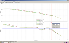
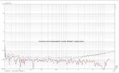
This next graph shows a single current pump, "rev-A modified" Evolution amplifier with the ADA4627 in it;
Note the general distortion level decrease; it's not principally due to the opamp change, it's mainly due to the compensation scheme (in case of LM318, the missing 470k had raised the loop gain in the circuit, for the low frequencies)
This amp is already without dc-servo -- the beneficial effect is clear;
Though here I'm cheating, the full story is that already the changes applied to the servo in the rev-A modification had resulted in a nice quality jump; It had been still rising towards low frequencies but much less and much smoother;
Attachments
A note: to compensate for my 'cheating', in this link the graphs had been made with an EVO still with LM318, single pump / double pump, and obviously already with rev-A mod in place. (directly comparable with the first graph here)
http://www.diyaudio.com/forums/chip...rallel-86-vs-sympatico-vs-14.html#post4732772
http://www.diyaudio.com/forums/chip...rallel-86-vs-sympatico-vs-14.html#post4732772
Last edited:
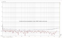
and finally the Evolution amp with double current pump and OPA827:
The contribution of the double current pump is visible in the high frequency region: the higher gm due the double pumps in the output stage is converted in higher loop gain at higher frequencies, and as a consequence better distortion suppression.
The contribution of the double current pump is visible in the high frequency region: the higher gm due the double pumps in the output stage is converted in higher loop gain at higher frequencies, and as a consequence better distortion suppression.
Attachments
For illustrating the effect of this compensation cap, I have done a scan of the loop gain changing as this compensation cap is changed. What is shifting more importantly is the phase margin of the composit loop.
The 627 is similar in many ways to the 4627; the effect, the direction of change is the same in all cases.
Watch the phase margin values in a, b points, the Y value is the phase margin at 0dB loop gain cross level.
Ciao, George
Wow! I had not even thought about this issue. Based on your graph, I can completely understand why a compensation cap is sometimes needed. Actually, I find it a little scary that we have about 50 dB open loop gain with a phase margin of only about 20 degrees in the region of 40 - 50 kHz (without comp cap). That seems a little thin to me.
This seems like a good reason why this mod should be a special mod, not just standard build. Anyone can do it, but you have to be careful, just as you said.
Thanks for the insight.
Jac
possible, but...
By raising the input filter cap value, and lowering R12, you are pointing to an ideal drive condition, with very low generator impedances. Now this can or can not be true. Modern Dac outputs directly applied to the amp would satisfy;
Any potentiometer would heavily disqualify; tube pre outputs (kohm range) would result in some khz total bandwith, I'm afraid..
But even soundcards, usually are having a couple of hundred ohms as output impedance.
So for this reason I see the 220pF filter cap as a more generally applicable, and usual solution..Ciao, George
Thanks again, George. Do I understand correctly that the output impedance of the generator adds to the value of R12, then combines with C12 to form the upper bandwidth limit?
The only universal solution I can think of is another high quality opamp used as a buffer between the input and the R12/C12 filter. I'm guessing that would overall be a worse result for both noise and distortion.
There is usually a good reason why component values are chosen. That's why I am not shy about asking questions when the alternative is to turn electronics into smoke.
Jac
PS Nice comparison of the Evo configurations. It really does show the progress of this design.
Could be low level oscillation - the fix is a small circa 3.3pf cap between pins 2 and 6 of the ADA4627.
I made some test on my ADA4627 My_ref boards.
A 4,7pF cap across pins 2 and 6 lowered the offset a bit (to around 130 mV peak), but didn't solve the problem. Nor did removing C13.
Anyway, offset slowly rises from switch on, reaches a peak level, then slowly goes down. When i say slowly, i mean it takes nearly 10 min to reach the peak, then more than an hour to go down to low levels (about 20 mV).
The only test that managed to bring offset to zero was bypassing R13, but i guess that can't be done if i want the amp to play good...

Dear Luca,
You just got mail with my analysis..
I would repeat here in short, because it might be interesting:
The scope shots provided by Luca did not show oscillations with a level equivalent to the observed offset; instead from the trace one can read a DC offset level equal to the meter-readout of Luca -- ~40mV this time.
This offset disappear when R13 is shorted. This shows that it only develops on the high input resistance (100kohm) of R13.
For me it's pointing towards a DC leakage current present.
This all concludes to two possible variants:
--An ESD discharge damaged the chip that it developed this faulty input current;
But both chips contemporary?!
--During the procedure of placement & soldering the chip some flux residual had been left back, which developes a leakage to the neighburing +Ve supply. This current developes an mV level offset voltage which than gets amplified on the output.
So my suggestion is: a thorough wash procedure for the board.
Looking forward!
Ciao, George
Last edited:
Would like to add: I have corrected, the leakage is towards the +Ve pin, that is from pin 2 to Pin 7, which is just the opposit side.
This points to a leakage path that is right below the chip: The wash procedure should reach there, like forcing with air pressure?
Ciao, George
This points to a leakage path that is right below the chip: The wash procedure should reach there, like forcing with air pressure?
Ciao, George
I used 300r and 2n2F on a power amp recently even though the designer specified quite different values..................
Has anyone considered changing R12/C12 from 3.3k/220pF to 330R/2.2nF, for example? I am probably missing something, but it seems like it shouldn't change the circuit performance other than a possible noise improvement.
Jac
This does rely on a fairly low source impedance
eg adding on the Source impedance of 220r, when fed from a DCB1 changes the filter to 220r+300r & 2n2F to give a roll off of ~ 140kHz (only 7times the 20kHz, rather than the full decade).
In addition I installed 47pF at the input socket which with the 220r gives a second pole rolling off at 15MHz
I don't want mobile phones and wireless gadgets interfering with my sound system.
There is a potential performance improvement coming from this different combination. Most power amplifiers prefer the base of the input transistor to see a low impedance. This reduces noise, distortion and improves stability on some amplifiers.
The 3k3 & 330pF gives a source impedance of 3k3||330pF, whereas the new version presents the base with 330r||2n2F
Roughly 10% at all frequencies.
Last edited:
- Home
- Amplifiers
- Chip Amps
- My_Ref Fremen Edition - Build thread and tutorial