I continue with the design, step by step.
Now I am with the bias voltage source for the XOR gates and the IR2110 driver. It must be 15V referenced to -Vcc (-50V in my case). To avoid using a second transformer or a linear regulator (too high a voltage), I was thinking on using a 1.5W zener diode as the reference, biased by a 1K/2W or so resistor and with a big cap in parallel to provide a reservoir of current.
The simulations are fine, but, as you introduce the ESR of the capacitor, with high loads (short 7.5Amp peaks in order to model the mosfet driver current draw), the supply has too much ripple.
What is the ESR that I should expect from a normal 100-1000microF capacitor at about 200-300KHz? What do you think of this solution?
Thanks!
Hi ssanmor
Are you driving your mosfets without any series resistor at the output of the 2110 ? I would strangly recommend to use some.
Also you should definitely use a decopupling cap across the 2110 that has low inductance.
I would build a "handsewn" series regulator to supply the driver and auxiliaries rather than just a resistor and a Zener.
Another question: Do you live in Europe ? If yes, I could send you two Siemens ferrite cores by mail that I once received as samples, so you can wind your own inductors.
Regards
Charles
Hi Alll...
"The disadvantage is that you can't synchronise multiple amps to the same frequency (or even to an integer multiple or divider of an SMPS switching frequency), which could reduce IM problems on the supply rails (which in turn can feed through to the output)."
ABOUT IT:
See also (only casual similarity)http://www.classd.org/oem_products/products/philips_dsl.htm
Regards
IVX
Back again
Hello all again!
Well, back to work after a few days of rest
I will continue my testings from now on, once my schematic is reasonably closed. As soon as I have a set-up, I will tell you.
This is my setup:
-Topology: Full bridge Class D with +/-30V rails by the moment.
-PWM generated by triangular wave (MAX038) compared with input signal summed to feedback (taken before the filter).
-The PWM is single ended, then level shifted by transistors and applied to XOR gates to generate the inverted version and adjust the dead-time (refer to my previous posts).
-The driver stage is based on a IR2110 chip. Mosfets: NTP32N15.
-Output filter: 4 pole L-C with a notch section.
Next step is setting up the power supply and be able to clean the triangle signal a bit.
I will keep you updated.
Sergio
subwo1
The thing with the tantalum as reservoir capacitor seems to be a good idea. Crest is doing the same. When I was playing around with a first generation IR2110 about 15 years ago I often encountered latchup of the whole amp after it was driven into clipping. Enough capacitance helps to avoid that (amongst better feedback topology than I used).
ssanmor:
Good luck with your project.
Regards
Charles
To make things clear: I was playing around with Class-D about 15 years ago when suddenly the IR2110 came onto the market. It was a huge progress compared to the discrete solutions I tried before (multiple CD4049 inverting buffers etc) but I still encountered problems.
Also the first versions of the 2110 had some properties that were not as good as today's versions (specially the delay matching of the two drivers) so I used a different approach for the amp that I developed some years later at the school of engineering (for schematic see one of my earlier posts).
If I were to develop a class-d amp again (which would definitely be interesting, but I don't have the time to do so) I would of course use an IR 2110 driver (or maybe the Harris one).
The subject of class-d amps is still an intriguing one after all these years. That's the reason I also did a lot of mindwork in this area (specially regarding feedback topologies) since then.
Regards
Charles
That time was when I began working on a class D design. But I was trying to convert a standard linear amp circuit over. They are too slow for that.
Having time to do everything is definitely a problem. Also, I didn't begin using the IR2110/3 until a couple of years ago, after they had been improved.
Having time to do everything is definitely a problem.
Also, I didn't begin using the IR2110/3 until a couple of years ago, after they had been improved.LAB.gruppen
Just incase anybody is wondering how 3400 watts fit in just 10 Kilos, LAB Gruppen is a swedisch manufacturer of pa amps who is using something called class td (patents apply) which as far as I understand is a combination of a class H with a class D design where the classH supply rails are replaced by a class D modulated power supply.
Just incase anybody is wondering how 3400 watts fit in just 10 Kilos, LAB Gruppen is a swedisch manufacturer of pa amps who is using something called class td (patents apply) which as far as I understand is a combination of a class H with a class D design where the classH supply rails are replaced by a class D modulated power supply.
Re: LAB.gruppen
This method is is one I considered many years ago, but I ruled it out as being more complex than needed because the switching supply would tend to interfere with the linear amp. The switching supply's high frequency components will tend to pass through the output devices of the linear amp to the speaker unless the audio amp has a tremendous frequency response to reject them. Furthermore, each amp needs to be composed of two amps, the audio and the switching, resulting in maybe twice as much circuitry. Thanks.
chriscam said:Just incase anybody is wondering how 3400 watts fit in just 10 Kilos, LAB Gruppen is a swedisch manufacturer of pa amps who is using something called class td (patents apply) which as far as I understand is a combination of a class H with a class D design where the classH supply rails are replaced by a class D modulated power supply.
This method is is one I considered many years ago, but I ruled it out as being more complex than needed because the switching supply would tend to interfere with the linear amp. The switching supply's high frequency components will tend to pass through the output devices of the linear amp to the speaker unless the audio amp has a tremendous frequency response to reject them. Furthermore, each amp needs to be composed of two amps, the audio and the switching, resulting in maybe twice as much circuitry. Thanks.
There are quite some manufacturers using tracking power supplies.
Maybe the most famous one is the Carver Sunfire amp.
Another one is the BASH amplifier technology. Their website is quite informative and IMO they are quite honest when it comes to comparing it to other topologies.
IMHO it should be possible to build a pure switching amp that is comparatively good as an amp with a tracking power supply. These won't get around the two worst disadvantages of switching amplifiers anyway:
1.) Switching residuals that might disturb low level signals and 2.)sluggish response due to the necessary output filter.
There is however a switching topology that sacrifices some efficiency but doesn't have these two disadvantages:
A linear amplifier of high bandwidth and high peak-current capability is assisted by a switching current-dumping amplifier. I know of at least one patent describing such an amp. And the Technical University of Vienna did some studies (and conference papers) regarding such topologies.
If there is any interest then I can add simulation results for better understandability.
Regards
Charles
hello phase,
I have some experience with Vienna amp. The main problem is that linear stage has to have extremly low open loop output impendance at switching frequency, otherwise you will have considerable amount of switching ripple at the output. I tried with MOS FET output stage, and got 0.5 V ripple at the output. Frankly, I did not use 2 phase switching stage with current ripple cancelation as is recommended in article. I also think bipolar voltage follower output stage would be far more appropriate.
Funny thing with tracking power supplies is that if you do your job well, then tracking power supply is already perfect switching amp. Every tracking power supply needs output filter with coresponding phase shift and associated loop compensation problems. It is very interesting that it is possible to compensate resonant peaking of output LC filter so you have linear frequency response regardless of load and that it was invented for tracking power supply by Carver corporation. The same principle can also be applied to any switching amplifier and requires only simple capacitor in feedback path from output filter to input of PWM modulator. Carver patent would allow that and it is interesting that no switching amplifier uses it.
Best regards, Jaka Racman
Hi Jaka
I haven't studied the Carver patent, but there are many known principles for taking feedback from the output filter (PID, multiple feedback loops, compensation of output filter LTF.....).
Fully load independant is none of them however but they can be made quite robust. Depending upon principle you can even compensate for the output filter's frequency response drop at the cost of higher susceptibility to TIM.
I haven't tried the parallel hybrid amp for the reasons you mentioned: The demands on the linear amp are quite stringent.
Regards
Charles
Hi,
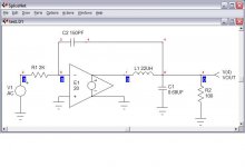
for anyone who is intersted how to damp output filter's resonance here is a simple spice model and results. Pwm output stage is modeled by ideal voltage source with fixed 20x gain. This is valid up to 1/2 switching frequency anyway. Output filter is a typical value of 22uH and 0.68uF and is far underdamped by 100 Ohm load resistance. 150 pF feedback capacitor does the magic. Try to remove it and you will see ringing in transient response and peak in frequency response. Interesting thing is that this works with any pwm modulator principle (triangle carrier or self oscillating). To my knowledge it has not been patented anywhere and from this post on it may be considered public domain knowledge .
for anyone who is intersted how to damp output filter's resonance here is a simple spice model and results. Pwm output stage is modeled by ideal voltage source with fixed 20x gain. This is valid up to 1/2 switching frequency anyway. Output filter is a typical value of 22uH and 0.68uF and is far underdamped by 100 Ohm load resistance. 150 pF feedback capacitor does the magic. Try to remove it and you will see ringing in transient response and peak in frequency response. Interesting thing is that this works with any pwm modulator principle (triangle carrier or self oscillating). To my knowledge it has not been patented anywhere and from this post on it may be considered public domain knowledge
.Attachments
- Status
- This old topic is closed. If you want to reopen this topic, contact a moderator using the "Report Post" button.
- Home
- Amplifiers
- Class D
- My very first Class D pwm (switching) amplifier.