Hi All,
ssanmor, 350mVrms ripple at 250KHz-very good (you_can_synchronise.gif circuit is the Sharp corp. TV class D amp and have 1000mVrms ripple at 150KHz, my amploiD-2000mV@80-100KHZ). I have never used the diodes in parallel with the mosfets too, but class D jedi ` s spoke to me about it:
" Good MOSFETs are STP14NF10 from ST. They are fast and produce very little radio interference. Adding fast diodes does not help in 300kHz applications because of the short dead time and the inductance of the MOSFET pins, so the internal diode of the MOSFET must be soft recovery. This ST fet has this. "
2Jaka Racman,
I not sure that link exist also my right to distribute this .pdf too... sorry (can ask the author?). about amploiD schematic/PCB no problem-Email.
Regards.
I would be very glad if you could send me or post the schematic/PCB of the AmploID design. Is it yours? I will do the same when mine is finished.
If you want my e-mail address, it is ssanmor@canal21.com
Best regards.
If you want my e-mail address, it is ssanmor@canal21.com
Best regards.
 I wan´t one too! I wan´t one too!!
IVX,
thanks for the offer but I am currently building digital class D amplifier based on TAS5015 modulator. If I can synchronise TAS5015 it will be 3 phase phase shifted stereo design, othervise it will be a nice 5.1 surround amp.
I am curious if attached picture is a UCD amplifier? It is from Bruno Putzeys article in IEEE Spectrum.
Best regards, Jaka Racman
Attachments
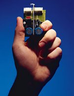
According to http://www.classd.org the UCD principle must be one of the simplest AND best sounding amps ever.
So the picture of the simple amp might show such a one.
I by myself haven't heard anyone of those so far (not even a SODA ), so I can't comment any further.
Are you talking of what I do privately or as a hobby ?
Regards
Charles
So the picture of the simple amp might show such a one.
I by myself haven't heard anyone of those so far (not even a SODA
), so I can't comment any further.Charles, what is your current dedication? Just for curiosity ;-)
Are you talking of what I do privately or as a hobby ?
Regards
Charles
Hi All.
Oui, cela - UcD l'amplificateur... alas, I didnt listen too it and slightly doubt, UcD sounds so well or Tip Voigt enthusiasm so much more.
I ` ll wait when Philips will make some TDA **** based under UcD concept. MUETA ` S circuit seems not so secret and after reading AES white paper, right now soldering are possible. Interestingly as well MUETA sounds, in fact not all of linear amplifiers with deep feedback are cool (feedback sound), or it not affected for class D? What do you thing?
Regards.

hi IVX,
may I suggest reading a classical paper about distortion in switching amplifiers:
http://ece-www.colorado.edu/~rwe/papers/CIT82.pdf
best regards, Jaka Racman
may I suggest reading a classical paper about distortion in switching amplifiers:
http://ece-www.colorado.edu/~rwe/papers/CIT82.pdf
best regards, Jaka Racman
Talking of feedback: It is not simple (but of course possible) to achieve huge amounts of feedback with ordinary switching topologies.
But it is also difficult NOT achieving 90 degrees of phase margin with simple class-d topologies. While it is hard to achieve 90 deg pahse margin for most non-switching amps, it comes almost for free with clas-d amps !!
Insuffiecient phase margin is one of the reasons for NFB sonics (".... feedback will always be toooooooo late, bla bla !" etc etc).
BTW: A very precise PWM modulator can be much more linear than many conventional VAS.
Regards
Charles
hi Jaka Racman,
thx, but this article is out of theme, imho, and class D now not so bad in ordinary distortions sort (THD.002@20-20000 etc). It is interesting for me why these amplifiers were not distributed quickly and widely right now if they few years are so good and cheap?
hi Charles,
Clear please that you mean- ordinary switching = simple class-d topologies =PWM? Self oscillating topologies are included?
conventional VAS-what is it (tube amp)?
& so cool PWM can be NFBless of course, but it really exist?
Regards.
hi IVX,
article correctly identifies some of distortion origins such as crossover distortion, distortion due to input filter impedance etc. Neglected is distortion due to switching transistors dead time and finite transition times. It also deals with open loop triangle modulated pwm stage.
Modern amplifiers achieve low distortion figures by use of NFB. But it is still a good thing to design power stage so as to have low open loop distortion. What can be learned from the article is:
-Heavy bypassing of power supply. Switching power supplies with LC output filter may be problematic if filter impedance is to high.
-Use of mosfets with low Rdson. Thus you prevent body diode from turning on and eliminate crossover distortion.
Why a those amplifiers not yet distributed? Mueta is still in developement stage, they promised to have chips in August. About UCD you probably know more. BO Icepak modules probably cost too much. There are no more designs with so low distortion figures. Another problem might be reliability ( I doubt that UCD has short circuit proof output) and EMC problems.
Best regards, Jaka Racman
Self Oscillating Class D
Hi Charles
This circuit is closer to what I hope to try out if I get the chance. I have added phase compensation to the feedback circuit. Without it, I fear high amplitude oscillations could develop without a speaker connected. I have also input the audio at the summing node. I am not sure where it would actually work out better to input the signal, at the negative or positive input pin.
I like this concept because for a sub amp I hope to be able to use a relatively large output choke, L7, for efficiency purposes. One very good reason to take the feedback after the output choke, if the circuit can be tamed, is for not only the high NFB obtainable, but also for the high damping factor operating on the speaker that should be had in the process. Otherwise the large choke could add a lot of distortion.
Also, with class D, it easier to run the power supply rails higher than with other topologies because the on/off nature does not significantly increase power dissipation in the output mosfets. The extra headroom allows the feedback circuit room to control the inductive speaker through a large sloshy choke. To prevent running the output to the higher supply rails inadvertedly, the input can be clipped at the appropriate level.
I like to use air core chokes for linearity and their unsaturable nature.
I wind air core chokes in such a way that half of the windings are in one direction and half in the other. One can simply wind it in two sections on a form, slide out the form, and double the choke back at the middle. This way should cancel EMI at a distance.
Attachments
 hi all
<I doubt that UCD has short circuit proof output>-easy, and much more for this cost (= good beer bottle) by discret smd parts and brain-nothing of superfluous. Haw DSLab could make it?...i am still shocked.
Regards.
ps: amploiD design sended to 3 mails &
"R36 & C25 - needed for <+/-40v." realy is "R36 & C25 - needed for >+/-40v." of course!

Hello all.
Yesterday I built and tested my revised version of the amplifier. The main changes from the original were a more exhaustive bypassing of all the supplies, substitution of the zener by a 7815 regulator to get 15v over the -Vss line in order to supply all the output stage logic, and using a 4-pole filter instead of the 2-pole one.
The results were good, the ripple much smaller (but not the calculated level), but I identified two problems:
a) When connecting the feedback with C1=1nF, the amplifier failed to oscillate. However, I changed it to 2.2nF and it worked fine. This failure appeared also in the previous version. What can the cause be?
b) I measured a noticeable amount of switching noise at the audio input. I connected a CD player headpone's output. The level of the ripple is proportional to the output current, hardly noticeable when no sound is present. I have to identify where this noise comes from. Perhaps from the feedback?
When I have those problems solved, I will publish the complete schematics and, if you want, the board design (2-sided).
Best regards and thanks to everybody who has helped me make this amplifier a reality.
Sergio
IVX:
I have been having a look at your amp. Some points seem interesting:
First, you have used a driver chip that requires only one PWM signal, managing the inverted version and the dead-time automatically. Simple and effective solution! By the way, there is another version (IR2184) that can give up to +/-1.7A thus not requiring buffer transistors (just for information).
Another thing you could explain to us is the feedback method. You feed the low frequency signal and sum it with the very output of the amplifier. Then you also feed the square wave from the totem-pole and also the output from the filter to the comparator via three different paths. A bit complicated for me!
What is the output ripple level?
The power supply is also interesting. I designed and built a very similar one (but based on SG3525) for a car amplifier. I published it in Rod Elliot's page. You can see it at:
http://sound.westhost.com/project89.htm
Best regards.
Sergio
hi ssanmor
A) You cannot expand frequency response for feedback indefinitely highly. If to use faster mosfets, driver etc and more Fsw then ok.
B) On my experience only mosfets and driver by switching dont produce noticeable noise. Lower input gain need to avoid noise.
Regards.
A) You cannot expand frequency response for feedback indefinitely highly. If to use faster mosfets, driver etc and more Fsw then ok.
B) On my experience only mosfets and driver by switching dont produce noticeable noise. Lower input gain need to avoid noise.
Regards.
Hi subwo1,
I started simulating self oscilating amplifiers. I was particularly interested in single feedback from output filter. I found out that I eventually came to the same shematic as yours. Simulation seems very promising, but there are some unexpected results. If I take into account propagation delay from the comparator to the output of the half bridge, say 200 ns, then output impedance becomes negative, that is you get more voltage at the output with heavier loading. Otherwise it seems very stable, also with no load, square wave response is stable with no overshot regardless of loading, seems that output filter is perfectly damped. Have you actually built one ? I am sure it will work, because it has recently been patented (us6420930, 6476673, 6489841) and also monolithic controllers exist http://www.monolithicpower.com/webaudiofamily.htm. BTW, my simulation shows that you can omit R5, that is also consistent with above patents.
Best regards, Jaka Racman
ssanmor
The driver chip (IR2111) is a good choice for subwoofer application, but I think it is troublesome to use in fullrange designs, as the deadtime is too long and not adjustable.
But IVX's design is very smart. Simpel and lowcost.. And VERY good performance as sub. amp.
Koldby
The driver chip (IR2111) is a good choice for subwoofer application, but I think it is troublesome to use in fullrange designs, as the deadtime is too long and not adjustable.
But IVX's design is very smart. Simpel and lowcost.. And VERY good performance as sub. amp.
Koldby
I think the same, the deadtime is too long.
My design has adjustable dead-time. I have found that the best results (minimal idle consumption) for full-range application is about 120ns, using a conventional PWM design with feedback from the totem-pole. The sound is very good as far as I have measured it.
Best regards.
My design has adjustable dead-time. I have found that the best results (minimal idle consumption) for full-range application is about 120ns, using a conventional PWM design with feedback from the totem-pole. The sound is very good as far as I have measured it.
Best regards.
- Status
- This old topic is closed. If you want to reopen this topic, contact a moderator using the "Report Post" button.
- Home
- Amplifiers
- Class D
- My very first Class D pwm (switching) amplifier.