I have the intention of using this LNA as a GP lab amplifier, and it has to remain well behaved for all conditions, including various source impedances.
Maybe I searched with the wrong words?
Anyway, if such a solution exists, I would be glad to know about it.
Yes at the time it was thought that one would not need a 1nV amplifier to measure the noise of large real source impedances. Did you try a cascode on the FET? Something like a J310 with high Vgs could be used with no additional components.
Yes, it already has a cascode (a BJT, but it doesn't matter), and there is only one opamp in the feedback loop.
All of this contributes to mitigate the issue, but not in eliminating it.
The rest still has to be tackled by brute force (zobel in // with the input works best)
All of this contributes to mitigate the issue, but not in eliminating it.
The rest still has to be tackled by brute force (zobel in // with the input works best)
Funny, I also wanted to revive this thread.
I'm trying to flush my pipeline of semi-completed projects.
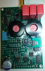
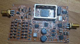
I have made a respin of the IF3602 amplifier with bipolar cascode.
The cascode is bootstrapped to effectively remove Cgd.
Cgs is taken care of by the usual feedback to the source.
It is somehow funny that gate, source and drain voltage wiggle in unison.
But the signal out of the FET is a current into the cascode emitter, so
this is not a show stopper.
My problem is that I really want at least 1 MHz bandwidth for my
phase noise measurements. Slightly above 1 MHz the bootstrapping
collapses and that results in a notch above the passband.
The inductor in the base of the cascode is essential. It must not be
anything lossy, both parallel and serial Rs make the input impedance
of the amplifier go negative somewhere.
I dropped the bias servo. The amplifiers input capacitor must be much
bigger for noise reasons than for BW. That creates an unneeded lower
corner frequency. The bias servo would have to be even slower than this
or it would interact with the amplifier.
So I went for a fixed gate bias. Between 0 and 60°C the drain current would
double. I did not like that and implemented some temp compensation consisting
of -2.5V from a TL431 and a BAV99 diode. That does the correction to the
first order, as far as simulation goes.
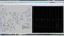
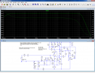
In the simulation, you can see that the generator voltage, source and drain
are the same in value and phase up to at least 700 KHz.
The top red line in the simulation is the input impedance. The phase would
jump from 0 to 180° if the impedance would turn negative.
That is not hard to accomplish. Part values interact quite heavily.
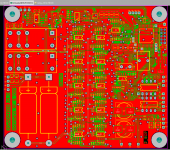
In the top left corner of the board there is also a JFET buffer from DC with
very little gain. I need that to measure the sensitivity of my phase comparator.
There is also a transmission gate to lower the 10Meg bias resistor to speed up
finding the operation point when we are far off. The window comparator is
at the bottom right.
Noise density is < 160 pV/rtHz over most of the frequency range.
Drain current is 55 mA for the 4 FETs together. The coolers are there
only to provide thermal mass.
I'm trying to flush my pipeline of semi-completed projects.
I have made a respin of the IF3602 amplifier with bipolar cascode.
The cascode is bootstrapped to effectively remove Cgd.
Cgs is taken care of by the usual feedback to the source.
It is somehow funny that gate, source and drain voltage wiggle in unison.
But the signal out of the FET is a current into the cascode emitter, so
this is not a show stopper.
My problem is that I really want at least 1 MHz bandwidth for my
phase noise measurements. Slightly above 1 MHz the bootstrapping
collapses and that results in a notch above the passband.
The inductor in the base of the cascode is essential. It must not be
anything lossy, both parallel and serial Rs make the input impedance
of the amplifier go negative somewhere.
I dropped the bias servo. The amplifiers input capacitor must be much
bigger for noise reasons than for BW. That creates an unneeded lower
corner frequency. The bias servo would have to be even slower than this
or it would interact with the amplifier.
So I went for a fixed gate bias. Between 0 and 60°C the drain current would
double. I did not like that and implemented some temp compensation consisting
of -2.5V from a TL431 and a BAV99 diode. That does the correction to the
first order, as far as simulation goes.
In the simulation, you can see that the generator voltage, source and drain
are the same in value and phase up to at least 700 KHz.
The top red line in the simulation is the input impedance. The phase would
jump from 0 to 180° if the impedance would turn negative.
That is not hard to accomplish. Part values interact quite heavily.
In the top left corner of the board there is also a JFET buffer from DC with
very little gain. I need that to measure the sensitivity of my phase comparator.
There is also a transmission gate to lower the 10Meg bias resistor to speed up
finding the operation point when we are far off. The window comparator is
at the bottom right.
Noise density is < 160 pV/rtHz over most of the frequency range.
Drain current is 55 mA for the 4 FETs together. The coolers are there
only to provide thermal mass.
Attachments
Last edited:
Funny, I also wanted to revive this thread.
I'm trying to flush my pipeline of semi-completed projects.
I have made a respin of the IF3602 amplifier with bipolar cascode.
The cascode is bootstrapped to effectively remove Cgd.
Cgs is taken care of by the usual feedback to the source.
I would think a high Vp FET cascode with gate tied to the source would at least be some help in the first circuit.
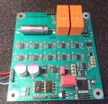
I have also made a new version of my 20xADA4898 preamp. It has now
the wet slug tantalum on the board and some protection circuits with
relays. On the op amp side, the stress is divided over 20 shoulders,
but with the patched old version, I managed to vaporize a LED whose
noise I wanted to measure.
Closing & opening the relays requires some discipline, best handled by
a computer. Gain and bandwidth can now be cold switched by transmission
gates. The small CPLD implements an SPI receiver and decodes the
control lines for the relays and analog switches. There are opto couplers
for the SPI interface. It is also possible to use mechanical switches instead
of SPI.
Attachments
I have made a respin of the IF3602 amplifier with bipolar cascode.
The cascode is bootstrapped to effectively remove Cgd.
Thank you for this. What is the capacitor C12 parallel to D1 good for ?
Funnily enough, the fix I have found and that seems to work is exactly opposite: reverse-boostrapping the cascode transistor: it neutralizes the Cgs capacitance by the equal Cgd.
It works in spice, but real world could be different due to phase-shift of a real opamp. And with my circuit, I will need one more opamp, because I don't have an inverting output available, but since it only exist in sim at the present time, it doesn't matter much
It works in spice, but real world could be different due to phase-shift of a real opamp. And with my circuit, I will need one more opamp, because I don't have an inverting output available, but since it only exist in sim at the present time, it doesn't matter much
Attachments
I would think a high Vp FET cascode with gate tied to the source would at least be some help in the first circuit.
I had tried that, it was not very convincing because of the low gm that left
a lot of AC voltage at the drain. I used some depletion FETs, IIRC
DN3525, DN2470, BSP149 etc.
For most types, the pinch-off voltage is also not very predictable.
< dn3525_bsp149 | Gerhard Hoffmann | Flickr >
Last edited:
Thank you for this. What is the capacitor C12 parallel to D1 good for ?
I have no idea how the Zener behaves at RF. And since even small resistors in series
to the base inductor have a bad influence on the stability, I included it as a forward defense.
A much smaller value does not seem to make a difference.
I'm just beginning to test the amplifier. It is not yet proved in any way.
Last edited:
I had tried that, it was not very convincing because of the low gm that left
a lot of AC voltage at the drain. I used some depletion FETs, IIRC
DN3525, DN2470, BSP149 etc.
I'll believe that, I was hoping with the SK170 that it might have helped enough.
@Elvee beware of neutralization there can be some unexpected effects like excess current noise due to charge pumping.
This summer, I have also built the preamp proposal from Horowitz/Hill,
Art Of Electronics V3.
< DSC_0467 | Gerhard Hoffmann | Flickr >
plus pics to the left/right.
It really does the 70 pV/rt Hz, but input impedance is quite low.
I only built the single sided half with 16 transistors, the differential
version with 64 transistors for the same noise would not help me
to avoid the input capacitors when the signal source is not centered
around 0V.
That was a test balloon for my chopper with SMD versions of the transistors;
there the coupling caps are not much of a problem because of the higher
chopping frequency.
Hi, Waly, I miss you!
Attachments
Last edited:
This summer, I have also built the preamp proposal from Horowitz/Hill,
Art Of Electronics V3.
< DSC_0467 | Gerhard Hoffmann | Flickr >
plus pics to the left/right.
It really does the 70 pV/rt Hz, but input impedance is quite low.
I only built the single sided half with 16 transistors, the differential
version with 64 transistors for the same noise would not help me
to avoid the input capacitors when the signal source is not centered
around 0V.
That was a test balloon for my chopper with SMD versions of the transistors;
there the coupling caps are not much of a problem because of the higher
chopping frequency.
Hi, Waly, I miss you!
Waly is gone (he still has an account but is in lurk mode only), but one of his remote mentors is back. Smart guy, to bad his mouth is too big to get accommodated on this forum.
Jesus Gerhard das ist eine verrueckte Idee. If you put all those bipolars in the minimum voltage noise bias (that is, likely, around 10mA a pop) the current noise will be around 25pA/rthz, meaning that a 3ohm source impedance adds 3dB to the equivalent input noise. For measuring purposes, works for batteries noise, but that’s about it.
Did you get any low frequency flickers? These are killing me with both bipolars and jfets... when the total gain is over 80dB, and bandwidth down to 1Hz or so, they can saturate the output every 10 seconds or so. I suspect these are of thermal origin (although I found nothing about in the literature), since lowering the current (hence the heating) lowers these flickers to the point they are almost tolerable. I was though unable to find any way to completely eliminate them other than limiting the low frequency response to 10 Hz or higher.
I suspect these are of thermal origin (although I found nothing about in the literature), since lowering the current (hence the heating) lowers these flickers to the point they are almost tolerable.
There isn't much beyond shielding all metallic connections from the cooling effects of air convection. This reduces random thermocouple variance. I always thought that if you have a heat flux there must be a statistical variation in temperature but I don't know enough physics to translate this into a number. I was asked this by one of the EE's at MTS Instruments years ago who observed that no matter how much care he took the difference of operating temperature of his instrumentation amplifier to ambient related to the low frequency fluctuations. BTW he was instrumenting those massive counterweights that go on top of skyscrapers to mitigate wind sway. You can imagine he was working <<10Hz.
The NIST guys got to 50pV using cross correlation and 100K averages measuring batteries.
Last edited:
Mechanicals/thermals discussed in this Jim Williams application note, appendix A:
https://www.analog.com/media/en/technical-documentation/application-notes/an124f.pdf
https://www.analog.com/media/en/technical-documentation/application-notes/an124f.pdf
Mechanicals/thermals discussed in this Jim Williams application note, appendix A:
https://www.analog.com/media/en/technical-documentation/application-notes/an124f.pdf
That’s a differential low noise input stage, much easier to manage. Single ended stages like Gerhard’s are a much bigger fish to fry.
I did not note any thermal effects after equilibrium. When the lids are bolted on, the preamp is quite a massive lump of metal.
These guys from ETH Zürich have invested a lot more in constant temperature:
< https://aip.scitation.org/doi/10.1063/1.4997963 >
Not so much for noise but for 100 fA DC input current with those fat IF3602 FETs.
I have also played with cross correlation in my 89441A vector signal analyzer, but the noise
became _so_ low that I did not trust the results and assumed operator error.
That damned thing has a lot of 1/f itself; that is currently my limit. I cannot increase
the preamp gain any more to hide it; there is not much dynamic range left. :-(
I have a LTC2500-32 coupled to the PRU of a Beaglebone Black, and the PRU
talks to the BBB's ARM CPU, and the ARM talks to my laptop over LAN. I also could
install FFTW on the ARM; that was easy since the ARM runs standard Debian Linux.
It is not much more than "apt-get install fftw."
Last edited:
There is not much self-invented to it, it is more of a software problem. The PRU is
a 200 MHz RISC without pipelining and thus with predictable timing, there is a
C compiler for it but the programs run somewhere deep in the guts of that TI system chip.
But you can toggle port bits at a 5nsec rate.
It is hard to talk to it until one has understood the shared buffers to the ARM and one
knows what variable ends up where etc. It did not help that they did a major operating
system cleanup at this time and most help from the internet was outdated.
The interface to user land is easy. Just open port 5025 on 192.168.178.66
and dump GPIB-like commands or read the time series in ASCII.
No secret USB drivers or things like that.
I could build there on a previous project. It is like talking to the 89441A.
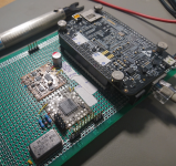
The stamp sized board in the back is the LTC2500-32 ADC.
it has 2 LTC3042 regulators and a negative one for the supplies,
a LT6655 reference and a fully differential input buffer like proposed
in the data sheet.
The stamp with the CPLD collects some random logic and converts the
100 MHz SPI to parallel bytes. (required for the full 1 Msps at "32" bits.)
a 200 MHz RISC without pipelining and thus with predictable timing, there is a
C compiler for it but the programs run somewhere deep in the guts of that TI system chip.
But you can toggle port bits at a 5nsec rate.
It is hard to talk to it until one has understood the shared buffers to the ARM and one
knows what variable ends up where etc. It did not help that they did a major operating
system cleanup at this time and most help from the internet was outdated.
The interface to user land is easy. Just open port 5025 on 192.168.178.66
and dump GPIB-like commands or read the time series in ASCII.
No secret USB drivers or things like that.
I could build there on a previous project. It is like talking to the 89441A.
The stamp sized board in the back is the LTC2500-32 ADC.
it has 2 LTC3042 regulators and a negative one for the supplies,
a LT6655 reference and a fully differential input buffer like proposed
in the data sheet.
The stamp with the CPLD collects some random logic and converts the
100 MHz SPI to parallel bytes. (required for the full 1 Msps at "32" bits.)
Attachments
Last edited:
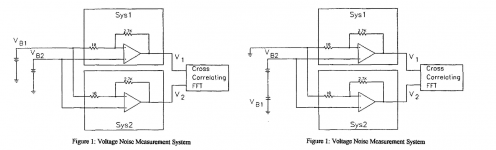
Am I missing something by rearranging the NIST battery noise test as shown?
I would assume an expected common mode output of 0 is a good thing.
Did YOU photoshop the alternative circuit? I can't see it in the original paper.
I think they are equivalent and that the common mode of 0 is nice to have.
I have duplicated the battery measurements with the 20xADA4898 preamp. That still had
the too small input caps at this time (as you did spot right away).
< http://www.hoffmann-hochfrequenz.de/downloads/NoiseMeasurementsOnChemicalBatteries.pdf >
Slightly less resolution, but batteries one actually can buy.
Last edited:
- Home
- Design & Build
- Equipment & Tools
- My version of the G = 1000 low noise measurement amp (for Ikoflexer)