whatever wherever hehe
even on bottom of the case just near the line pcb,with few drops of superglue and some thermal compound
I still prefer shunt reg,just because this little thiny preamp looks prety "vulnerable" and deserves best what we can achieve ;
serial reg with heavy shunt is just halfway this
if we make one decent supply-mebbe even owners of original NS10 can benefit from that (meaning that Treshold was ,after all , commercial company-with all limitations what that implies) ....
hey-I can bet that even your BOSOZ will sound nicer with shunt reg
Thanks TonyWhich etching solution are you using? Hope to do some as nice as yours, some day.
 I am using FeCl for the etching. I have both a 20k pot and a 10k. I will try both at input. My BoZ and BosoZ has them wired in at the output, so the circuit noise is attenuated when turning down. But this little wonder will not have any "Mosfet-hiss" will it
")
Yes the BosoZ psu can easily take 50mA for this little preamp. The "Twisted BosoZ" psu is nice indeed, but there may be other reg's performing better for this preamp. Choky could you post a schematic or a link to what you have in mind?shunt current-make it 30 or 50 mA
IMO the best place for the shunt resistor would be on the psu board, for practical matters. Just in case someone would use another psu that cant carry the shunt current.
Steen
thomasfw said:Dear Russ,
I found that the connection of C4 with Q1 is different than before.
Before is (B,E), now is B,C) !
Would you please check your "Copper Layout" again !
Thomas
Thomas, it looks correct to me, but I would ask other who know this type of circuit better then myself to help verify. I don't have the FETs ye to buiuld a prototype, so the PS is as of yet untested.
Thanks,
Russ
steenoe said:
Yes the BosoZ psu can easily take 50mA for this little preamp. The "Twisted BosoZ" psu is nice indeed, but there may be other reg's performing better for this preamp. Choky could you post a schematic or a link to what you have in mind?
Steen
http://sound.westhost.com/project37.htm
scroll down to psu pic (figure 3)
just a idea,I didn't checked exact psu,but I'm still for burnin' 50mA p/ch
looks familliar?
ps-ultimate PSU will be CCS followed with shunt reg
or-worse- serial reg followed with shunt reg
or - more worse - hehe- just shunt reg
or most worse
 serial reg
choky said:
I'm still for burnin' 50mA p/ch
Nice ideas Choky, could you propose someting specific for this aplication? double rail of couse.
apassgear said:
Nice ideas Choky, could you propose someting specific for this aplication? double rail of couse.
yo my man-who is da sand specialist here?
not me-fer sure!
what I can propose is so simple (almost replicated from tube world,where I just luuuve shunt regs ,because they are FAST and silent.
I give url to Mr. Elliot's site in my previous post- principle is there,and now someone else ( with better aknowledgements about prefered parts here on Diyaudio
) must do homework .....presume that one channel of NS10 eat 20mA;
so-we need our shunt to burn another 50 mA at least ;
we can make that in two ways-active or passive ;
if passive is in question,we can use resistor(parallel to active stage) of 25v/50 mA = 500ohms/3W
in front of that we can make one nice series reg (even with 317 ,but in that case we must use some series resistor ,to make things better right at the shunt (better isolation between stages,less influence of feedback based IC stage etc); that also demands some higher voltage right at the start of supply
same principle for lower part,just with 337instead of 317...
if we need things just complicated ,we can use active shunt (with voltage reference-so we don't need voltage reference in previous stage) ,just like on Eliot's site ,predecessed with CCS ,of any kind.
my brain is now something on 2/10 ,so I must go to sleepppppppppppppppppppppppzzzzzzzzzz
ps-if somebody gives me right amount of one channel consumption ,even from simulation,I can make few sketches of proposed supply
in any case-we can stick for starters with http://www.diyaudio.com/forums/showthread.php?postid=772973#post772973
and stitch one fat resistor on each rail .
later we can make additional shunt active reg
just to remind and make clear that to my self ,just before I fall in sleep:
one way is : CCS - then - active shunt reg (so voltage reference is here)
other way is : serial reg (voltage reference is here) - then - passive shunt
gone
capput
so loong post just because two last sentences.......

Its not that I like to add more alternatives for the psu, but I kind of like this one here: Zener-emitter follower Notice that this is not the latest schematic of this psu. A CCS device was added later (J511). See the silkscreen here:
Zener-emitter board I have just asked Alcaid to post the latest schematic for that circuit.
I posted a picture of that supply earlier in this thread.
I feel we have a good starting point with that one It can possibly be fine tuned a bit?
I will install the preamp today, and try and see if it is saying anything.
BTW, The mailserver has been down I guess, I didnt receive any mails for a while, since sometime yesterday.
Steen
Zener-emitter board I have just asked Alcaid to post the latest schematic for that circuit.
I posted a picture of that supply earlier in this thread.
I feel we have a good starting point with that one
It can possibly be fine tuned a bit?I will install the preamp today, and try and see if it is saying anything.
BTW, The mailserver has been down I guess, I didnt receive any mails for a while, since sometime yesterday.
Steen
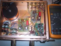
Okay guy's, we have a working preamp There was no problems at all implementing this little wonder The sound is very promising, indeed. With a better implementation than this proto, I wouldn't be surprised if this will be a very well sounding preamp I am running it from a simple LM317/337 supply at +/- 22v, since Choky didn't like my other supply (I am inclined to try it anyway's though) The parts used for the boards, were just some components I had on the table. The pot is a 10k Elma attenuator wired in at the input. The transistors are MPSA18 for Q1 and Q3, Q2 is a BC560C. (watch the pinout if you will use these, as they doesnt fit the silkscreen!!) Turn it 180 dg. The trimpot is 200k. All component values as per schematic. I guess this means we can safely move on, and see if something can be perfected, somehow. The foundation should be OK Here is the prototype, dont mind the build, it is really just a proto I will wait a bit, before committing to another build. Lets see what suggestions there is for improvements first.
Steen
Edit. The adjustment process is a little tricky. I managed to adjust both channels to 0v at the output. But the voltage drifts when turning it on and off. At turn on the voltage is positive approx 300mV, at turn of it goes negative to about -150mV. The circuit settles slowly. So be a bit patient when adjusting.
There was no problems at all implementing this little wonder The sound is very promising, indeed. With a better implementation than this proto, I wouldn't be surprised if this will be a very well sounding preamp I am running it from a simple LM317/337 supply at +/- 22v, since Choky didn't like my other supply (I am inclined to try it anyway's though) The parts used for the boards, were just some components I had on the table. The pot is a 10k Elma attenuator wired in at the input. The transistors are MPSA18 for Q1 and Q3, Q2 is a BC560C. (watch the pinout if you will use these, as they doesnt fit the silkscreen!!) Turn it 180 dg. The trimpot is 200k. All component values as per schematic. I guess this means we can safely move on, and see if something can be perfected, somehow. The foundation should be OK Here is the prototype, dont mind the build, it is really just a proto I will wait a bit, before committing to another build. Lets see what suggestions there is for improvements first.Steen
Edit. The adjustment process is a little tricky. I managed to adjust both channels to 0v at the output. But the voltage drifts when turning it on and off. At turn on the voltage is positive approx 300mV, at turn of it goes negative to about -150mV. The circuit settles slowly. So be a bit patient when adjusting.
Attachments
steenoe said:
Edit. The adjustment process is a little tricky. I managed to adjust both channels to 0v at the output. But the voltage drifts when turning it on and off. At turn on the voltage is positive approx 300mV, at turn of it goes negative to about -150mV. The circuit settles slowly. So be a bit patient when adjusting.
or simple timer for output (tyed to gnd) relay or servo as in SL10 or ......just nuuthin'
KISAS ?
Hi, Steenoe,
It works?
I don't know if I'm hearing wrong, but when I don't use the DC offset adjustment R (or VR) it sounds better for me. I can leave the DC offset (I got 500mV) because the output is cap coupled.
I know that Tmblack doesn't like Jfet for Q1, maybe you can try it? Jfet should have input/output transfer curve that is closer to ideal linear device than bipolars. Bipolars is exponential (too big), while Jfet is more ^3. Different devices for Q1 gives different sound, I got my joy experience changing Q1 from one to other kind of device. Even between bipolars with different HFE's the sound is quite different.
It works?
I don't know if I'm hearing wrong, but when I don't use the DC offset adjustment R (or VR) it sounds better for me. I can leave the DC offset (I got 500mV) because the output is cap coupled.
I know that Tmblack doesn't like Jfet for Q1, maybe you can try it? Jfet should have input/output transfer curve that is closer to ideal linear device than bipolars. Bipolars is exponential (too big), while Jfet is more ^3. Different devices for Q1 gives different sound, I got my joy experience changing Q1 from one to other kind of device.
Even between bipolars with different HFE's the sound is quite different.- Status
- This old topic is closed. If you want to reopen this topic, contact a moderator using the "Report Post" button.
- Home
- Amplifiers
- Pass Labs
- My Take on Threshold NS10