JC Fardo said:Mr. Pass himself.
I am convinced NP is a twin, the biggest audio secret.
Or triplets, "The Only One" is not enough for pumping out so much, so fast.
(either that, or God, but let's not go that stereotype road)
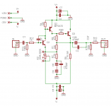
Thanks a lot, TomSome people want to try a FET for Q1. There is no change needed in biasing it.
")
JC, there was no psu posted yet, but someone will eventuallyIs there a NS10 PSU schematic around I´missing?
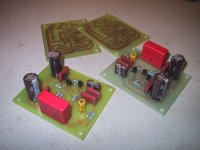
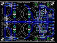
Here is a pic of the proto boards in the making. No fancy parts yet. The first test will be to see, if this works at all
Dont let Q2 confuse you, I have used a BC560C, which has a different pinout than the MPS4250. Where is best to wire the pot, for a circuit like this. Input or output?
Steen
Attachments
tmblack said:Some people want to try a FET for Q1. There is no change needed in biasing it.
Tom
EE
Thanks Tom, That's what we wanted to hear
Re: NS10 PSU schematics
I will propose a PSU soon. A double rail regulated supply similar to other Pass projects.
The actual demand of the circuit is very low so a small trafo will do, some 20/30 VA for both channels is enough.
JC Fardo said:
Is there a NS10 PSU schematic around I´missing? What could be the trafo VA rating?
JC
I will propose a PSU soon. A double rail regulated supply similar to other Pass projects.
The actual demand of the circuit is very low so a small trafo will do, some 20/30 VA for both channels is enough.

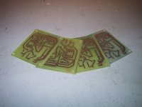
Tom, yes thats the tonertransfer method. Here is a link with a really good description of the process. The paper I used is called OCE glossy photo paper, IJ570. It was bought a couple of years ago, but I am not sure I can get that paper again.
http://www.fullnet.com/u/tomg/gooteepc.htm
Russ, thanks for the schematic. Yes that etch turned out pretty good. There is no problems populating the boards, so no muckups yet Here is a closer pic of the boards.
Steen
http://www.fullnet.com/u/tomg/gooteepc.htm
Russ, thanks for the schematic. Yes that etch turned out pretty good. There is no problems populating the boards, so no muckups yet
Here is a closer pic of the boards.Steen
Attachments
steenoe said:Here is a pic of the proto boards in the making. No fancy parts yet. The first test will be to see, if this works at all
Where is best to wire the pot, for a circuit like this. Input or output?
Steen
Steen,
I will say it again, your work is one of the best around. Absolutely very nice boards you did. Which etching solution are you using? Hope to do some as nice as yours, some day.

Regarding the pot position it’s a matter of preference and testing, but will also depend on your source output impedance. If you plan to use it with a highish source impedance I would try it at the output of the preamp. But otherwise I would put it at the front, guess that the original NS10 was also at the input.
For the front pot try a 20K and for the rear position I would start with a 10K and increase it to 20K if you think it’s to much load.
Thanks Russ for all the effort, think all is coming out nice
Next board iteration, after ironing other issues and of course after some testing results I would suggest you try to put all 3 transistors closer still, the closer you can. I think it would be well worth the effort.
Next board iteration, after ironing other issues and of course after some testing results I would suggest you try to put all 3 transistors closer still, the closer you can. I think it would be well worth the effort.
PSU
Russ,
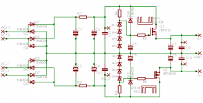
I think a good PSU for this pre would be what you have on the XBOSOZ. If you agree pls post the schematic for others to see.
For all of you:
Rails after regulation would be +25/-25V, so adjust zeners to have these voltages (some 28V zener stacks).
It would be a good idea to load the outputs of the regulators with some 10mA using a shunt resistor to get good voltage stability. This means to add a 2.5K resistor from rail to ground after the PSU output caps.
Russ,
I think a good PSU for this pre would be what you have on the XBOSOZ. If you agree pls post the schematic for others to see.
For all of you:
Rails after regulation would be +25/-25V, so adjust zeners to have these voltages (some 28V zener stacks).
It would be a good idea to load the outputs of the regulators with some 10mA using a shunt resistor to get good voltage stability. This means to add a 2.5K resistor from rail to ground after the PSU output caps.
Re: PSU
shunt current-make it 30 or 50 mA
piece of cake with this voltage and used (proposed) parts
3w resistor per rail will do the job
apassgear said:Russ,
I think a good PSU for this pre would be what you have on the XBOSOZ. If you agree pls post the schematic for others to see.
For all of you:
Rails after regulation would be +25/-25V, so adjust zeners to have these voltages (some 28V zener stacks).
It would be a good idea to load the outputs of the regulators with some 10mA using a shunt resistor to get good voltage stability. This means to add a 2.5K resistor from rail to ground after the PSU output caps.
shunt current-make it 30 or 50 mA
piece of cake with this voltage and used (proposed) parts
3w resistor per rail will do the job
- Status
- This old topic is closed. If you want to reopen this topic, contact a moderator using the "Report Post" button.
- Home
- Amplifiers
- Pass Labs
- My Take on Threshold NS10