Hi everyone,
Looks like an interesting design - However, I fear it may have a low gain margin (phase margin) and could lead to instability on some speakers...
Someone suggested a capacitor to form a HF feed-back loop just around the op-amp to avoid the phase lag of the output stage at HF.
Where would that go?
Jennice
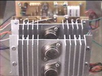
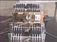
I tried the suggested 33pf on the opamp output to the inverting input and experimented up to 150pf. When using 150pf, the high frequency response seems to be becoming less harsh. I'll try more values but have run out of caps to use ") I also soldered it directly under the pcb.
I also soldered it directly under the pcb.
This prototype uses TO-3s for the ops.
Cheers!
JojoD
I also soldered it directly under the pcb.This prototype uses TO-3s for the ops.
Cheers!
JojoD
Attachments
Jennice said:Hi everyone,
Looks like an interesting design - However, I fear it may have a low gain margin (phase margin) and could lead to instability on some speakers...
Someone suggested a capacitor to form a HF feed-back loop just around the op-amp to avoid the phase lag of the output stage at HF.
Where would that go?
Jennice
Of yourse I didn't build this amplifier. I will do some adjustment to get the best stability.
The capacitor You asked, have to put between the -input, and the output of the opamp. Maybe some series RC network works too.
Sajti
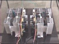
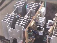
Now I'm working on PCB, and heatsink design. I planned to use 2x25cm heatsink for each poweramp, with fan cooling.
Good luck, I shall wait with great interest.

Attachments
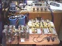
So, I put together the amplifier, Yesterday evening.
It works good, but not sound as good, as my low feedback amplifier. There is something - maybe distortion- at the top end. I checked with scope, and there was no ringing or oscillation.
I will try to make some fine adjustment today.
Sajti
It works good, but not sound as good, as my low feedback amplifier. There is something - maybe distortion- at the top end. I checked with scope, and there was no ringing or oscillation.
I will try to make some fine adjustment today.
Sajti
I will send some pictures, but now my amplifier looks very confused
I know what you mean! When I build an amp and tweak it, I come to a point when even I get confused when I look at the amp!

JojoD
JojoD818 said:Hi guys,
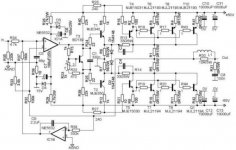
Thought I share this amp to my fellow diyers. Not that hard to build but it sounds good enough for me.
I've tested it with an OPA134 but even an LM301AN will work. Outputs in the prototype are MJL21193/4 (TO-264) but I've tried/tested MJ15003/4, MJ15024/5 (TO-3) with good results. That means it will work with anything you have laying around
Supply for the prototype is only +/-50V but has also been tested with a +/-70V. If you use the higher supply, better use a bigger heatsink.
Sound is, as I said, good enough for me. I'm planning on using this for mid-high applications but have also tried it for a 10" dual voice coil subwoofer.
JojoD
The reason that this circuit doesn't perform at higher freq. is the op-amp. Yes op-amps are wonderful, but there are so many transistiors integrated on the chip that miller capacitance will destroy your slew rate. I bet this circut has some harmonic distortion when pushed above 70-80 percent.

- Status
- This old topic is closed. If you want to reopen this topic, contact a moderator using the "Report Post" button.
- Home
- Amplifiers
- Solid State
- My recent power amp...