May I ask in what way have you used a 'potmeter'?
As a simple voltage devider. I "inserted" the potmeter between C1 and R1. (see pictures in next post).
The potmeter is a conductive plastic version by Bourns, PN: 95A1A-B28-B15L. The value is 10k.
Last edited:
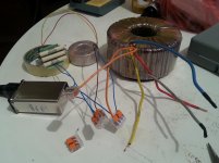
I've started building the second channel.
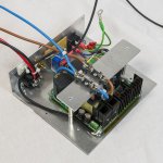
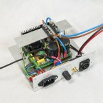
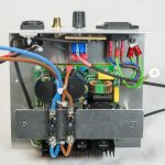
Over the weekend I did most of the mechanical part. Since I wanted to include a power LED I decided to mount the power supply horizontal.
That provides better access to the amplifier itself but also to the connectors at the back.
I still need to add the power LED in the first channel and in order to do that I’ll need to remove the power supply since it is blocking access to rear (due to it vertical position).
I’ll take that opportunity to change the position of the power supply to horizontal as well.
The power LED is a warm white and I’m using a 10k resistor to limit the current and therefore the brightness as well. I don’t want the LED to be too bright…
I will soon start populating the PCB of the second channel and finish the heatsink assembly of the second channel. Hopefully I’ll have some time over the weekend for that job.
Attachments
Bourns, PN: 95A1A-B28-B15L, not available in Farnell, will check for something similar and post suggestion here
Bourns, PN: 95A1A-B28-B15L, not available in Farnell, will check for something similar and post suggestion here
You could also use this one: 91A1A-B28-B15L BOURNS, Rotary Potentiometer, Conductive Plastic, 10 kohm, 1 W, ± 20%, 91 Series, 1 Turns, Linear | Farnell element14
It has different terminals but these are usable too.
Input Signal level
Hi delange, thanks for the Farnell info for another type.
In my case ill have both channels in one case so ideally i'd need one pot controlling both i/p levels together, being a 2-ganged type.
Problem is that there doesn't appear to be any 1 W's.
2 ± 20% 10kohm Linear Rotary Potentiometers | Farnell element14
By the way delange, what fuses do you suggest to use in the supply lines to the Q-Watt boards?
Have you used a Power on/off switch?
I'm currently mounting the transistors on the heatsinks, maybe i'll post some images tomorrow.
Cheers
Last edited:
In my case ill have both channels in one case so ideally i'd need one pot controlling both i/p levels together, being a 2-ganged type.
Problem is that there doesn't appear to be any 1 W's.
You don't necessary need 1W types; we are adjusting very low levels.
This could be a candidate: 3310H-001-103L BOURNS, Rotary Potentiometer, Sealed Panel Control, 10 kohm, 250 mW, ± 20%, 3310H Series, 1 Turns, Linear | Farnell element14
By the way delange, what fuses do you suggest to use in the supply lines to the Q-Watt boards?
Elektor suggests 10A slow blow. I currently have fast blow in my first channel (because I didn't have slow blow on hand). If you don't intend to play extreemly loud then the fast blows will work as well.
Have you used a Power on/off switch?
Since I'm using my amps behind the speakers I have no power switch fitted in the amp enclosure. Instead I use an external relay who is controlled by a 12 volts trigger signal of my preamp. My preamp switches the Q-Watt on and off.
I'm currently mounting the transistors on the heatsinks, maybe i'll post some images tomorrow.
Cheers
Looking forward to that!
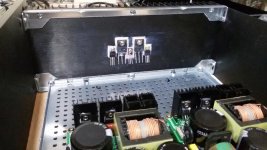
Mounted transistors
delange, thanks again for the info, have now added it to Farnell's basket with its knob 1209780.
I've got 10 amp anti-surge fuses, so will use these for now.
Can't seem to find a decent looking power switch, will keep looking in Farnell....If i find one might fit it on rear and just have a front led indicator.
Having never drilled to thread a hole, i was very anxious when i began, but its turned out alright, not forgetting to check their insulation afterwards.
Heatsink is a little messy from the heatsink compound...
Attachments
Last edited:
Hey guys. You both are making great progress. I'm trying to catch up before my electrolytics go off.
I am using a Shaffner FN9290 IEC power inlet and mains filter, with 2x fuses and integrated switch. Top quality but pricy. Switch will be on the back but it will give my kids less to play around with.
I tested my ESP soft start this week with an ancient ILP 625VA transformer. Starts up on 3.1A fuse no problem every time, and the resistor bank only heats up 1 deg C each start. Takes about 3 mins to lose the heat. I'm using 3x 10W 100R in parallel so peak current to the transformer is limited to 10A for the first few mains cycles. One minor issue with the ESP P39 soft start... it really needs more than 9V AC supply due to rectification losses. 10V AC would give close to 11.5V DC at the relays.
Pops.
Can't seem to find a decent looking power switch, will keep looking in Farnell....If i find one might fit it on rear and just have a front led indicator.
I am using a Shaffner FN9290 IEC power inlet and mains filter, with 2x fuses and integrated switch. Top quality but pricy. Switch will be on the back but it will give my kids less to play around with.
I tested my ESP soft start this week with an ancient ILP 625VA transformer. Starts up on 3.1A fuse no problem every time, and the resistor bank only heats up 1 deg C each start. Takes about 3 mins to lose the heat. I'm using 3x 10W 100R in parallel so peak current to the transformer is limited to 10A for the first few mains cycles. One minor issue with the ESP P39 soft start... it really needs more than 9V AC supply due to rectification losses. 10V AC would give close to 11.5V DC at the relays.
Pops.
Attachments
Last edited:
it really needs more than 9V AC supply due to rectification losses. 10V AC would give close to 11.5V DC at the relays.
Strange... with a 9 volts AC transformer you should have about 12,6 volts DC after the rectifiers and buffer caps. Did you meassure that?
Hi Delange,
Yep I measured 9.3V AC into the P39 board and 10.8V DC on the aux DC output. It has a tiny power supply with four discrete diodes and tiny buffer caps. (I have spare diodes so will measure Vf).
I think it was expected by the designer because Rod recommends a small 9V transformer. This would have about 12% regulation and 10.1V AC ouput at no load. I was scared of overheating relays with > 14V DC so I used an 8.5V (full load) transformer. Gives 9.3V AC whilst powering the board and relays, but the DC is lower than I expected. It could be cleared up if the silkscreen on the PCB said 10V instead of 9V.
I checked the 12V relay spec and I don't think it's a serious problem. Relay will trigger at >9V just takes a few milliseconds longer. And since the resistor network is not getting hot the soft start delay is obviously not 'too long'. Might even save some heat/power in the long term. Relays get quite warm (ambient +15deg) even at 10.8V.
Last edited:
The relay will trigger on 9Vdc. The specification probably shows a trigger value of ~60% of the rated voltage.
But as you have noticed it pulls in more slowly.
If your mains voltage drops as all mains does, you may have non trigger and that will leave your 3off 100r in circuit while the amplifier appears to be operating normally. This is likely to burn out the resistors.
I much prefer to use a higher voltage and regulate down to the relay's rated voltage.
I recommend going further: Regulate down to ~125% to 150% of rated relay voltage and then implement a current saving circuit.
eg, using a 12V 1000ohms relay use a lm7818 regulator fed with ~22Vdc, from 15Vac.
Add a series resistor of ~1k with the relay coil.
Trigger the relay from a capacitor charged to almost 18Vdc.
Then after the cap has discharged the coil current drops to ~9mA.
The relay runs cool and fires quickly and operates properly from all supplies from 216Vac to 253Vac.
You may find that the 625VA+33r33 soft start will reliably start up on a T2.5A fuse. Personally I would have used 4off 10r (in series) as the soft start added resistance. That would definitely start up on a 253Vac supply using a T2.5A mains fuse.
Last edited:
Hi delange, i can't for the life of me find those fuse holders you've used.
As i have other items to order from Farnell i would like to order from them.
As i have other items to order from Farnell i would like to order from them.
If your mains voltage drops as all mains does, you may have non trigger and that will leave your 3off 100r in circuit while the amplifier appears to be operating normally. This is likely to burn out the resistors.
I should get 9.4V DC even with 210V AC mains supply. And I went for 10W resistors which gives me a little margin for timing error. I'm not happy about being 1V off target though.
I love the sound of your regulated supply with a burst of current to trip the relay. Very smart. I'm only becoming aware of voltage regulators now... so for this project I wanted a lo-tech design. I will file this one for later!
You may find that the 625VA+33r33 soft start will reliably start up on a T2.5A fuse. Personally I would have used 4off 10r (in series) as the soft start added resistance. That would definitely start up on a 253Vac supply using a T2.5A mains fuse.
3.1A was the first fuse I tried... for sure I will try going lower for final installation. You might remember that the ultimate objective is to start 2x 432VA(ish) transformers. The 625VA is just to test out my design and measure the voltage losses before smacking up Paypal (lesson learned :-D).
I see I missed one comment.I should get 9.4V DC even with 210V AC mains supply. And I went for 10W resistors which gives me a little margin for timing error. I'm not happy about being 1V off target though.
I love the sound of your regulated supply with a burst of current to trip the relay. Very smart. I'm only becoming aware of voltage regulators now... so for this project I wanted a lo-tech design. I will file this one for later!
3.1A was the first fuse I tried... for sure I will try going lower for final installation. You might remember that the ultimate objective is to start 2x 432VA(ish) transformers. The 625VA is just to test out my design and measure the voltage losses before smacking up Paypal (lesson learned :-D).
Running a 12V relay at under 10V should not feel hot.
Maybe just slightly warm close to blood heat, rather than cold.
Can you check it is a 12V relay and measure the coil resistance?
140mW relays don't consume a lot of power, but if that is based on a 230Vac supply and you run at 246Vac, the relay will be quite a bit warmer (160mW).
Hi Calpe - switch is integrated into the mains inlet & filter:
http://www.mouser.co.uk/m_new/schaffner/schaffner-FN9280-module/
So that means it will be on the back. Suits me.
http://www.mouser.co.uk/m_new/schaffner/schaffner-FN9280-module/
So that means it will be on the back. Suits me.
Hi Andrew - I used 12V 16A relays with the high - sensitivity 540 mW coil. At 10.8V it's dissipating a little over 400 mW. The temp rise is expected: surface temp is about 33deg after 10 mins. If I remember... coil resistance is 270R.
That's what is pulling your DC voltage down.Hi Andrew - I used 12V 16A relays with the high - sensitivity 540 mW coil. At 10.8V it's dissipating a little over 400 mW. The temp rise is expected: surface temp is about 33deg after 10 mins. If I remember... coil resistance is 270R.
44mA current instead of 12mA current.
- Home
- Amplifiers
- Chip Amps
- My Q-Watt project