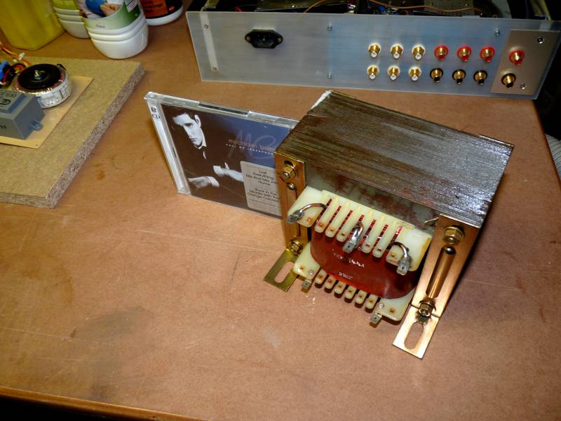
It's a long time ago that i purchase 3 symasym 1.3DTV Board....1.4 version was also provided since. For a couple of day i founded in a industriel rubish some parts nice parts i could use for 1.3DTV so i decided to go for.
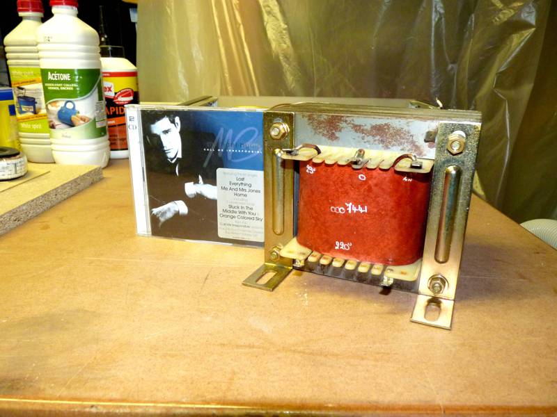
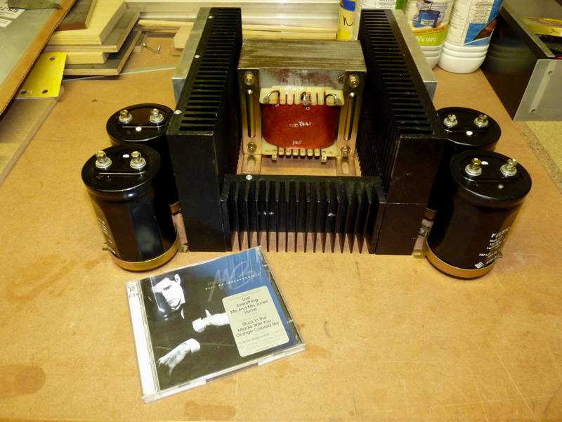
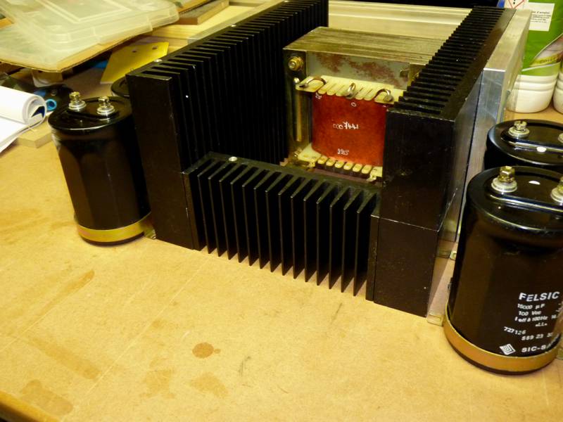
The first part was, comming from an industriel power supply, a nice EI trafo. Visualy i could say i rate over 600Va (steel dimension are w150xh130xd80mm) and 29-0-29V
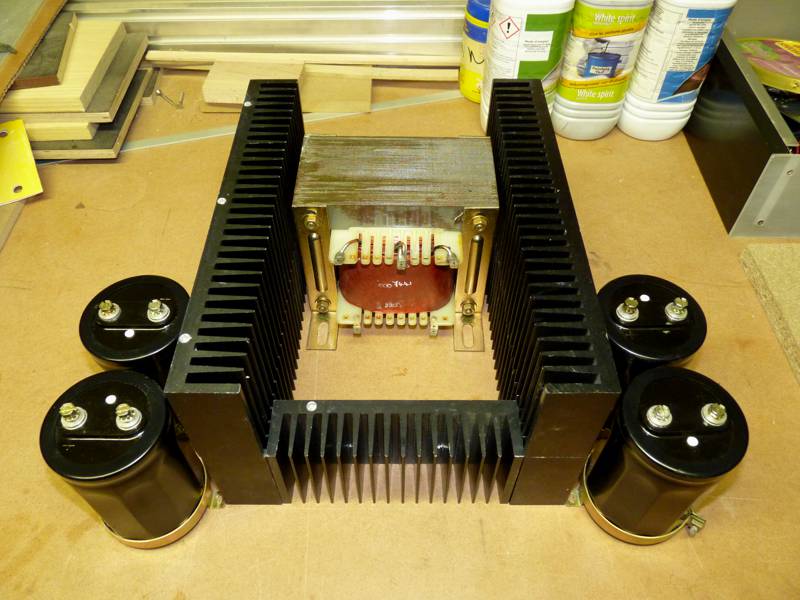
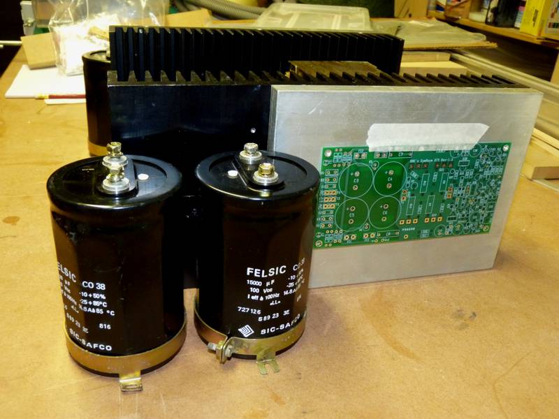
I founded nice smoothing caps too 15000µF/100V. I took out of my stock somme rubish heatsink (300x75x40mm) to constitute the base of a stereo symasym 1.3 DTV bloc.
I will take two heatsink per chanel and join them with a 10mm thick sheet of aluminium. The little front heatsink on following picture will host 2 MUR20W Rectifier bridge.
I have also 2SC1837/2SA4793 and matched MJL1302/3281, 2SK170BL. So i need to purchase 2N5401/2N5551 and match them and some minor electronic parts for building
Marc
The first part was, comming from an industriel power supply, a nice EI trafo. Visualy i could say i rate over 600Va (steel dimension are w150xh130xd80mm) and 29-0-29V
I founded nice smoothing caps too 15000µF/100V. I took out of my stock somme rubish heatsink (300x75x40mm) to constitute the base of a stereo symasym 1.3 DTV bloc.
I will take two heatsink per chanel and join them with a 10mm thick sheet of aluminium. The little front heatsink on following picture will host 2 MUR20W Rectifier bridge.
I have also 2SC1837/2SA4793 and matched MJL1302/3281, 2SK170BL. So i need to purchase 2N5401/2N5551 and match them and some minor electronic parts for building
Marc
Last edited:
My symasym is taking shape
Greetings all,
I thought I'd share my 1.3 DTV build progress with you all and get a few questions answered.
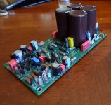
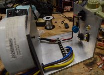
I used LSK370 because I had them from another project. I even remembered to reverse their direction on the board
I'm running off 27v rails; a bit low, but I think it should be okay.
I made an error in my parts order and ended up short a few caps. You can see my replacement in the first picture below (hint: it's bright yellow).
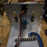
On to my question. In the assembly instructions AAK says to connect one of the on board ground pads to the heatsink. Instead of doing this I was considering connection my CT to ground (maybe through an NTC thermistor) at the terminal block. In my mind this creates something of a star ground. In the photos below CT is the blue wire. I still have to run ground from the IEC to the block and ground the chassis. Thoughts?
I will be posting more pictures when everything gets up and running.
Thanks all,
Nelson
Greetings all,
I thought I'd share my 1.3 DTV build progress with you all and get a few questions answered.
I used LSK370 because I had them from another project. I even remembered to reverse their direction on the board
I'm running off 27v rails; a bit low, but I think it should be okay.
I made an error in my parts order and ended up short a few caps. You can see my replacement in the first picture below (hint: it's bright yellow).
On to my question. In the assembly instructions AAK says to connect one of the on board ground pads to the heatsink. Instead of doing this I was considering connection my CT to ground (maybe through an NTC thermistor) at the terminal block. In my mind this creates something of a star ground. In the photos below CT is the blue wire. I still have to run ground from the IEC to the block and ground the chassis. Thoughts?
I will be posting more pictures when everything gets up and running.
Thanks all,
Nelson
Attachments
Last edited:
- Status
- This old topic is closed. If you want to reopen this topic, contact a moderator using the "Report Post" button.