Hi Piersma,
I'm away from home for the Thanksgiving holidays, I'll run the IMD test this weekend when I get back. Do you have any specific frequencies that you'd like me test?
Before I left I tested the new boards and everything looks great. I'll put you down for four boards.
Regards,
Al
I'm away from home for the Thanksgiving holidays, I'll run the IMD test this weekend when I get back. Do you have any specific frequencies that you'd like me test?
Before I left I tested the new boards and everything looks great. I'll put you down for four boards.
Regards,
Al
Hi Piersma,
Attached are the IMD plots you requested. For each picture the top plot is the IMD of the input signal, the bottom plot the output IMD. Each was taken using an 8 ohm load.
I'll start a group buy thread sometime this week. I have a count of six boards so far.
Regards,
Al
Attached are the IMD plots you requested. For each picture the top plot is the IMD of the input signal, the bottom plot the output IMD. Each was taken using an 8 ohm load.
I'll start a group buy thread sometime this week. I have a count of six boards so far.
Regards,
Al
Attachments
")
Hi Al,
Even with MJL3281A/1302A, the 50V rail voltage seems to high for me espacialy if speakers impedance is seeking near or under 4ohms....Will a 40-42V rail version not be more aware with output Device SOA : MJL4281/4302; MJL3281/1302; 2SC2922/2SA1216. I am not enough expert to indicate how to switch from 50 to 40-42V even nore if it's possible toward your design....
regards Marc
Hi Marc,
At 40-42V rails the amp should work fine into a 4 ohms or higher with the MJL devices. Now if you go down to 3 or 2 ohms then there is a good chance you’ll have a problem especially at high output levels. At 40-42V rails you shouldn't have to change any components values on the amplifier. Just use a 30-0-30VAC transformer and your all set
My new board with dual pair output transistors my do the trick for loads under 4 ohms, I'll be posting more information on that amp shortly.
Regards,
Al
Hi All,
Here a pictures of the dual pair transistor version of the design. I added 0.865" to the length of the board to accommodate the extra pair of output transistors. The board now measures 5.865" x 2.95" including the power supply. The new design does require a heatsink with a 4" height instead of the 3" like the single pair.
Regards,
Al
Attachments
Hi All,
Here a pictures of the dual pair transistor version of the design. I added 0.865" to the length of the board to accommodate the extra pair of output transistors. The board now measures 5.865" x 2.95" including the power supply. The new design does require a heatsink with a 4" height instead of the 3" like the single pair.
Regards,
Al
Have you proceed to transistor matching (front end or output devices)?
Marc
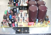
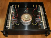
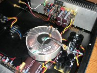
Here's another picture of the dual transistor version (DTV) using a single transformer and my external PS. The on board PS rectifiers are bypassed. This is a nice option to have if you have a single transformer with at least 450 to 500VA and would like to beefen up the power supply reservoir capacitance.
I get absolutely no AC hum even with the inputs floating and my ear nearly touching the dust caps. Pretty amazing! The sound just blows me away.
The question for those interested in the group buy, which amp would you prefer? I like the (DTV) because of the extra power, and the way it handles the low end of my MTM speakers.
Al
Attachments
Here's another picture of the dual transistor version (DTV) using a single transformer and my external PS. The on board PS rectifiers are bypassed. This is a nice option to have if you have a single transformer with at least 450 to 500VA and would like to beefen up the power supply reservoir capacitance.
I get absolutely no AC hum even with the inputs floating and my ear nearly touching the dust caps. Pretty amazing! The sound just blows me away.
The question for those interested in the group buy, which amp would you prefer? I like the (DTV) because of the extra power, and the way it handles the low end of my MTM speakers.
Al
It can depend on the need or not of output device matching, the possibility or not of using MT200 (Sanken) output device. I suppose that the DTV can switch to MTV by ommitting some parts. Why do you bypass the on board PS rectifiers? If it's necessary why implement it on board?
Regards Marc (very interested by this symasym upgrade)
Hi Marc,
This amplifier requires more transistor matching than most because of the cascodes. But you do have the option to bypass cascode Q3,Q4 in differential section, and Q9,Q12 in VAS section if you'd like. In the differential section without Q3,Q4 you'd have to drop the rail voltage to under +/-40V, +/-36V being optimum, or you can replace the 2SK170's with 2n5551 keeping the +/-50V rails but you would have to add an AC input coupling capacitor in position C25. I left out C25 on the schematic but it's on the board. You also don't need to match the output transistors if you use a single pair. The other transistors that need matching are Q1 and Q2, Q10 and Q11, and Q5 and Q6.
I'm not familiar with Sanken devices but I would be happy to provide you with a set of new Toshiba 2SA5200/2SC1943 for about two bucks a piece, and match all the small signal transistors for a small charge.
I've attached the on-board power supply schematic, and the DTV amplifier section schematic.
Regards,
Al
P.S. I'm calling this new version of SymAsym, SymAsym Plus. If anybody can think of a better name please enlighten me.
Attachments
- Status
- This old topic is closed. If you want to reopen this topic, contact a moderator using the "Report Post" button.
- Home
- Amplifiers
- Solid State
- My new SymAsym PCB design Rev_1.3