I've done 71A with 22mA and 47 triode strapped with 15mA. Easily manageable; both do ok with only 310 V or so B+.
I consider the 71A the most linear and best sounding American DHT tube there is (not counting transmitting tubes). Although I haven't ever tried the 300B - too expensive. Some day...
I've got a quad of 46's, haven't tried them yet. 47's are easily as good as 2A3 in my opinion.
2A3 will do just fine with 35mA current though.
Couldn't find data on 4N1P?
When I say slow start-up, I am thinking of at least 30 seconds.. I sometimes use a 1 min delay (after heater turn-on) on top of that.
Why do you need/want a 30s delay?
Why do you need/want a 30s delay?
Not delay, slow start-up. To be honest, 30+ seconds slow start-up is probably ok without the extra 1 min. time delay. I just don't want my full B+ on cold cathode, and I want my 2a3 grid bias to come up with my B+ nice and steady.
Do you have a tube tester? How much time does it take for most DHT heaters to start to fully conduct? About 1 min for that heater to get hot from my experience - but if they are older DHT's then it can take longer. For that I add the 1-3 min. delay switch ($10 time delay switch on fleabay).
This amp is directly coupled, so the bias must be present for that B+... A nice solution is for it to come up slowly with the B+. If it is not present then the tube won't conduct and the B+ will keep going up and up!!!
If you use silicon diodes to rectify then you must at least have a delay before turning on B+. I would make it 1 min (or maybe more just to be on the safe side). Full B+ from silicon diode rectification will spike hard, and the grid bias voltage will not be there yet, so the B+ could easily go way up over 500V for a short time.
I think EC810 once noted this: "the dimmer the filament, the more succeptable to cathode stripping". That makes sense to me.
Sy once said this: "My own experience has been that for most tubes, it isn't a problem except at higher plate to cathode voltages." Which also makes sense to me.
In my most humble opinion with 2a3 and Loftin White, both of these statements must be considered to avoid cathode stripping.
Last edited:
Do you have a tube tester? How much time does it take for most DHT heaters to start to fully conduct? About 1 min for that heater to get hot from my experience - but if they are older DHT's then it can take longer. For that I add the 1-3 min. delay switch ($10 time delay switch on fleabay).
I don't have a tube tester. The russian DH tubes I use are low filament current, and they heat up in a matter of seconds. Maybe 5 s at most. Now that I think of it, the 26, which is a highish current DHT, took maybe 10 to 20 seconds to heat up. 71A was more quicker.
The circuits I used / use are such that the heat up time doesn't really matter for the circuit.
With the Darius follower, the 2A3 grid is essentially at ground potential before the 6SL7 comes online. This limits the 2A3 current to a small amount.This amp is directly coupled, so the bias must be present for that B+... A nice solution is for it to come up slowly with the B+. If it is not present then the tube won't conduct and the B+ will keep going up and up!!!
Without it, taken from premp plate, you have a more dangerous situation. Then the 2A3 will conduct like crazy, before preamp starts conducting and plate voltage / 2A3 grid volta drops to normal.
Like I originally suggested, gyrators solve these problems. If the preamp tube has a gyrator plate load, it's plate voltage is the same cold or warm (there's a 10 V difference because of that one resistor, it's meaningless in this context). Even if you don't have the preamp tube in the socket, the voltage is there, right from turn on (with that 1 to 2 s ramp up I described).
Regarding cathode stripping: In a non-regulated, resistor plate loaded circuit, the tubes can experience high voltages during turn on. My SE amp has about 450V raw B+ unloaded; that's a lot for a cold tube. However, since there's a regulator, the circuit B+ is never over 310 volts.
Also, since all the tubes have gyrator plate loads, their plates cannot see (in DC conditions) higher voltages than what the gyrators have been set to put out. So it's 180V at turn on; even cold, the tubes have absolutely no problem with that voltage. No stripping at all possible.
Regs and gyrators protect the tubes during turn on by limiting the voltages to go no higher than normal operation.
Last edited:
Dear Curwen
Unfortuately Gyrators are useless things in this design. I like the idea, but the heat sinks required would need to be VERY VERY big. You admit this yourself but then go on to write about their merits.... I don't doubt them.
They solve no "problems" and only create new ones. I doubt they could be used on the 45 even, but maybe it has been done by someone....
I won't comment on the 71a, which is a BEAUTIFUL tube. Its not a 2a3 or a 45 though. What do you bias it at? do you use filament bias perhaps? If so it is somewhere much close to ground - correct? It won't risk seeing 500VDC A-K in your circuit - correct?
Anyway, the 71a will not offer enough power for my 94dB speakers... That's a pity. I like it. I like Gyrators. They won't work here though.
Most respectfully, please do not encorage readers to try gyrators on this direct coupled 2a3 design - UNLESS you try it yourself first and post some pictures of your success. That would convice me. I would be very Happy!!!!")
Unfortuately Gyrators are useless things in this design. I like the idea, but the heat sinks required would need to be VERY VERY big. You admit this yourself but then go on to write about their merits.... I don't doubt them.
They solve no "problems" and only create new ones. I doubt they could be used on the 45 even, but maybe it has been done by someone....
I won't comment on the 71a, which is a BEAUTIFUL tube. Its not a 2a3 or a 45 though. What do you bias it at? do you use filament bias perhaps? If so it is somewhere much close to ground - correct? It won't risk seeing 500VDC A-K in your circuit - correct?
Anyway, the 71a will not offer enough power for my 94dB speakers... That's a pity. I like it. I like Gyrators. They won't work here though.
Most respectfully, please do not encorage readers to try gyrators on this direct coupled 2a3 design - UNLESS you try it yourself first and post some pictures of your success. That would convice me. I would be very Happy!!!!
Last edited:
Dear all
After some listening, especially to chamber music and Opera, I must admit that the 2nd version of the power supply is much more revealing and musical sounding. This is kind of sad, since the 1st version was much simpler and cheaper....
I wish that I could do it with Gyrators and solid state. So far it still has to be proven as reasonably possible.
I don't have a tube tester.
I highly recomend getting a decent one if you wish to practice this hobby seriously. Beyond that, an osillioscope is very useful as well. Get as good a one as you can find.
Best regards
Last edited:
The only "modern enhancement" on this circuit I could imagine is a CCS in the cathode of the follower. That would make the whole circuit draw a constant current at all times, which further relaxes psu requirements.
Yes, I have considered that as well. I actually have a few measured and ready to go... just too busy enjoying the sound right now though. Maybe tomorrow.
Ian
I've been toying with the idea of building my own tube tester. I frankly can't justify making it; I try out new tubes in a test circuit, and if one of them is too out of line, I toss it. Other than that, my circuits don't really require any kind of matching of tubes or such. A useful enough scope I've got; one of my customers bought it for me as a bonus. =)I highly recomend getting a decent one if you wish to practice this hobby seriously. Beyond that, an osillioscope is very useful as well.
I would agree. Possibly replace the 2A3 cathode resistor with a CCS as well, so that it won't self destruct even if 2A3 grid voltage is not ok for any reason.The only "modern enhancement" on this circuit I could imagine is a CCS in the cathode of the follower. That would make the whole circuit draw a constant current at all times, which further relaxes psu requirements.
However, I do not agree that that particular circuit is the BEST there is to be had with these tubes in SE. If this thread is limited to that particular circuit design, then ok, but other than that I personally think it's good to throw around ideas and suggestions, and debate their merits. I've started out with direct coupled SE amps, and step by step done different things with them (now I've mainly done balanced amps for a while, in preparation for ESL times ahead). Different things are not for everybody, but they are for some people; maybe some people in this thread. Maybe not.
You raised some issues regarding turn on; I adressed them. Those issues are separate from whether or not gyrators are practical in a certain situation or not, and should not have been left unanswered.[T]he heat sinks required would need to be VERY VERY big. You admit this yourself but then go on to write about their merits.... I don't doubt them.
Properly ventilated, 10W is doable. Sinks would be about the size of a fist, maybe a bit more for safety. Not insanely big. Practical? Probably not.
Depends on what is a 'problem'. For me, 20dB of harmonics is a serious problem. Also lowering the amp's output impedance is important for me.They solve no "problems" and only create new ones.
But, in the end, every single design has pros and cons, and every builder must pick what they're willing to compromise on, and what not.
If I read you correctly, you're doubting whether it is possible to make a good sounding and working amp with gyrator plate loads on a 45?I doubt they could be used on the 45 even, but maybe it has been done by someone....
Why wouldn't it be? I've used this kind of circuit myself on a number of tubes. I've gravitated towards low current, low power types, since me and my customers don't need much power, and it's easier to stay away from big heat.
I won't comment on the 71a, which is a BEAUTIFUL tube. Its not a 2a3 or a 45 though. What do you bias it at? do you use filament bias perhaps? If so it is somewhere much close to ground - correct? It won't risk seeing 500VDC A-K in your circuit - correct?
In the context of using gyrator plate loads, I first used the 71A in a direct coupled SE amp with (completely and utterly insane) LED bias. 150VDC on grid, 190VDC on cathode, and B++ was about 500V. Next I moved to fixed bias, and discovered source followers. They returned the direct coupled sound, and did it even better.
I've done a fixed bias gyrator plate load with 300 to 650 volts B+ on a number of tubes since then. Cathodes at ground, grid fed from source followers.
My current best amp has direct coupled 4P1L in a balanced circuit. Their cathodes are at 200VDC, and grids at 180VDC. B++ is 515 V.
I don't have any 2A3 at hand at this time, but I'm game for a gentlemanly challenge.Most respectfully, please do not encorage readers to try gyrators on this direct coupled 2a3 design - UNLESS you try it yourself first and post some pictures of your success. That would convice me. I would be very Happy!!!!
Would it be satisfactory if I build a single ended 6SL7 (gyrator loaded) direct coupled to a parallel'd pair of 1626 with op point 250V a-k, 60mA combined current thru the pair, gyrator plate loaded?
I could parallel a couple of 6V6GTs. Or maybe a 47, I've done that before as well.
I'll build it this weekend, and provide pictures, some measurements and video of actual audio coming thru it. Maybe I'll roast a sausage on the heat sink. =)
Last edited:
Hi Curwen, sounds like your direct coupled 4P1L deserves its own thread.
Power supply semantics aside, the clever bit about this circuit is the noise cancellation and the bootstrap follower which creates that most unexpected high load you mentioned a few posts ago. Most who look at the circuit don't understand what is happening and dismiss it as a simple cathode follower... I'm not sure where 20dB is happening in your simulation. Goldenbeer's simulations did not reveal such things.
1626 is another lovely tube. It would be a pity to parallel it though.
Last edited:
I do not agree that that particular circuit is the BEST there is to be had with these tubes in SE
Please do note that I never made such a claim. Is this amp is one of the best SE that I ever built? sure. The best in the universe? That's a pretty big claim!
But I now look very much forward to your schematic with pictures of your build.
This is a DIY board so do feel free to share.If this thread is limited to that particular circuit design, then ok
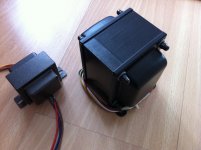
The original topic is of course about the new J&K output transformers I have. Perhaps we should get back to that. They are sounding superb now that they have had some time to run in!
I almost don't want to hook up the Tangos to compare... but rest assured I will do that soon.
Last edited:
Keep in mind that "resistance at the plate" is with self bias and not cathode bypass. The normal "Rp" as shown on data sheets is, I believe, calculated with a bypassed cathode.
Sheldon
This is indeed the case for the GE and Tung-Sol datasheets.
Last edited:
However, I do not agree that that particular circuit is the BEST there is to be had with these tubes in SE.
I can't remember anyone making that claim. I do believe however, that this circuit - to borrow from scientific language if you don't mind - that this circuit represents a local maximum.
You raised some issues regarding turn on; I adressed them. Those issues are separate from whether or not gyrators are practical in a certain situation or not, and should not have been left unanswered.
Look at the protection diode in my circuit. This should take care of any hard turn on issues as well.
Depends on what is a 'problem'. For me, 20dB of harmonics is a serious problem.
If you are referring to your sims, at such low distortion levels, the tube models and simulations are notoriously unreliable wrt distortion levels. You need to resort to real world measurements. But then, you would probably only find that in this case, distortion varies more between different brands, samples and batches of tubes than the circuit topologies discussed or anything else...
Rgds
GB
Been thinking of trying a 2.4k resistor on the plate of the bootstrap follower, which would make it more in line with what Darius built. I noticed this morning that I am actually using 2.4k grid stopper on the bootstrap follower, not that it should make any difference as compared to the schematic as drawn. I probably did it without even thinking abut it...
I might as well try a higher value bootstrap capacitor as goldenbeer has suggested too, as well as the CCCS. Its a rainy day here...
I might as well try a higher value bootstrap capacitor as goldenbeer has suggested too, as well as the CCCS. Its a rainy day here...
Dear All
Well I finally got around to hooking up my Tango XE-20s OPT's to compare with the J&K ALIS-5SE. I had both set to 3.5k:8 Ohm outputs just to make the comparison as fair as possible.
The J&K transformers can be found here: J&K Audio Design while Iso Tango is unfortunately no longer in production. The chief reason I waited to compare the two was to give the J&K's time to run in.
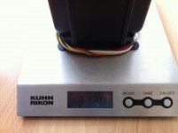
Its always hard to be subjective about these things. I must admit that I love Tango OPT's, especially the FX-40-5 (for P-P) and the XE-20s (for SE). With this design they don't dissapoint. The XE-20s weighs in just over 2Kg and has enviable sonic characteristics.
Its really hard to pick a winner here. When I play vinyl, close my eyes and relax, it feels like the musicians are rigtht there in front of me. Even CD's sound really life-like.. I would perhaps say the XE-20s has a slightly more delicate, forward presentation. The ALIS-5SE has a slightly more impressive, richer sound stage. Bass response is steady and firm for each OPT, and both freely pass all the musical details and transients that surprise and delight a listener.
I prefered the ALIS-5SE for popular music over the XE-20s because of the slightly more impressive sound stage. Pink Floyd and AC/DC never sounded so darned good. The slightly more delicate presentation of the XE-20s was the winner for solo guitar and female vocals. It sounded like Diana Krall was in our living room. Lots of goose-bumps were felt with each OPT... The differences are very small and quite subjective though - highly dependant on source too.
I also hooked them one to each channel, and played some mono recordings. Darned hard to tell which one I would prefer. Thelonious Monk, Vienna Quartet, mono Doors and Hendrix... All sounded fresh and like I had never really heard them before.
The XE-20s takes up less space and is a whole Kilogram lighter than the J&K. I would probably chose it if space and weight are a concern. That said, the XE-20s is not in current production and I hate auction bidding wars. I think if space on the chassis is not a concern then the J&K is an excellent choice.
You need to give new OPT's time to run in though, and there are other superb winders out there. Its wise to investigate, ask questions and compare first.
Just as a reference, I hooked up the little Tomiko OPT's again too. Surprise suprise, they sounded pretty darn good! Lively and fun, but they don't compare to the other two which are in a completely different league...
Hope this is useful for others.
Well I finally got around to hooking up my Tango XE-20s OPT's to compare with the J&K ALIS-5SE. I had both set to 3.5k:8 Ohm outputs just to make the comparison as fair as possible.
The J&K transformers can be found here: J&K Audio Design while Iso Tango is unfortunately no longer in production. The chief reason I waited to compare the two was to give the J&K's time to run in.
Its always hard to be subjective about these things. I must admit that I love Tango OPT's, especially the FX-40-5 (for P-P) and the XE-20s (for SE). With this design they don't dissapoint. The XE-20s weighs in just over 2Kg and has enviable sonic characteristics.
Its really hard to pick a winner here. When I play vinyl, close my eyes and relax, it feels like the musicians are rigtht there in front of me. Even CD's sound really life-like.. I would perhaps say the XE-20s has a slightly more delicate, forward presentation. The ALIS-5SE has a slightly more impressive, richer sound stage. Bass response is steady and firm for each OPT, and both freely pass all the musical details and transients that surprise and delight a listener.
I prefered the ALIS-5SE for popular music over the XE-20s because of the slightly more impressive sound stage. Pink Floyd and AC/DC never sounded so darned good. The slightly more delicate presentation of the XE-20s was the winner for solo guitar and female vocals. It sounded like Diana Krall was in our living room. Lots of goose-bumps were felt with each OPT... The differences are very small and quite subjective though - highly dependant on source too.
I also hooked them one to each channel, and played some mono recordings. Darned hard to tell which one I would prefer. Thelonious Monk, Vienna Quartet, mono Doors and Hendrix... All sounded fresh and like I had never really heard them before.
The XE-20s takes up less space and is a whole Kilogram lighter than the J&K. I would probably chose it if space and weight are a concern. That said, the XE-20s is not in current production and I hate auction bidding wars. I think if space on the chassis is not a concern then the J&K is an excellent choice.
You need to give new OPT's time to run in though, and there are other superb winders out there. Its wise to investigate, ask questions and compare first.
Just as a reference, I hooked up the little Tomiko OPT's again too. Surprise suprise, they sounded pretty darn good! Lively and fun, but they don't compare to the other two which are in a completely different league...
Hope this is useful for others.
Attachments
Last edited:
Ok, long awaited here is the 2nd generation power supply.....
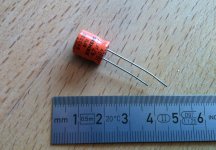
What type of capacitor is C4? I assume that C3 is your usual ASC motor run.
JM
Hi JM
C4 is the only electrolytic capacitor, and you only need it on one channel. I put it on the right channel. All other capacitors are motor run or polyester film.
The value of C4 is not very critical - 10uF would also be a fine choice. It should be at least 100V rated. Mine is rated 160V. It is used to reference the 6SL7 heaters to 65-70V.
Attachments
- Status
- This old topic is closed. If you want to reopen this topic, contact a moderator using the "Report Post" button.
- Home
- Amplifiers
- Tubes / Valves
- My New Iron for Single Ended 2a3