

These are my broad band speakers. The cabinet holds 25 liters, the back has a 22% opening (here) compared to the front hole. The published F-res of this speaker is 60Hz.
Other speakers I connected were KEF 102 (with and without Kube). Both pairs share the loud, exaggerated bass reproduction when connected to the 2A3 amp. Mids and highs are lovely as a SE should be but bass notes are offending. Perhaps I'm not a 2A3 man?
Not sure what it is disco. I use full range Cabasse (98dB - full range no crossover) in my office to test with and Living Voice OBX in my living room (94dB - were kinda expensive but I'm a no-talent at speaker build).
I don't have any booming bass at all and have been listening to things like Bob Marley this morning to try and push it...
I don't have any booming bass at all and have been listening to things like Bob Marley this morning to try and push it...
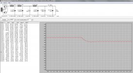
Ok, long awaited here is the 2nd generation power supply. I will admit it is still not ideal but it is pretty darn good.
Its a flywheel type using two Lundahl LL 1694 Filament Chokes, then splitting right and left channel to a Lundahl LL 1638. The LL 1638 I had here is the 8 Hy version, so each channel is using 4 Hy. If I had a 10Hy LL1638 it would be better.
PSU II can't do a very good job at modelling the effect of each channel, so I put in a current tap after the 2nd choke to simulate the effect of the other channel.
I use the soft start option in PSU II since I am using Damper Diodes. The real measured B+ voltage is around 404 volts right now. Each 2a3 is drawing a little over 48mA. I will probably make some more adjustments.
You can see that a significant change in current draw results in a pretty clean 20mS response. The serial resistance is really low and the response is FAST. The most significant way to reduce the response time further is to go to solid state diodes, but then this simulation immediately shows significant overshoot, and you lose the slow start-up (which is very important). The plate resistance of the 6AX4 damper diode is around 120 ohm while the 6AU4 is less at about 80 ohm, so just by using 6AU4 the B+ can be set higher.
Those who use more solid state materials in their power supply can adjust for all of these shortcomings one way or another. That might be fun to try some time in the future. Right now I am enjoying this little amp a LOT.")
My next report will be on how the Tango XE-20S sounds compared to the J&K.
Its a flywheel type using two Lundahl LL 1694 Filament Chokes, then splitting right and left channel to a Lundahl LL 1638. The LL 1638 I had here is the 8 Hy version, so each channel is using 4 Hy. If I had a 10Hy LL1638 it would be better.
PSU II can't do a very good job at modelling the effect of each channel, so I put in a current tap after the 2nd choke to simulate the effect of the other channel.
I use the soft start option in PSU II since I am using Damper Diodes. The real measured B+ voltage is around 404 volts right now. Each 2a3 is drawing a little over 48mA. I will probably make some more adjustments.
You can see that a significant change in current draw results in a pretty clean 20mS response. The serial resistance is really low and the response is FAST. The most significant way to reduce the response time further is to go to solid state diodes, but then this simulation immediately shows significant overshoot, and you lose the slow start-up (which is very important). The plate resistance of the 6AX4 damper diode is around 120 ohm while the 6AU4 is less at about 80 ohm, so just by using 6AU4 the B+ can be set higher.
Those who use more solid state materials in their power supply can adjust for all of these shortcomings one way or another. That might be fun to try some time in the future. Right now I am enjoying this little amp a LOT.
My next report will be on how the Tango XE-20S sounds compared to the J&K.
Attachments
Last edited:
These are my broad band speakers. The cabinet holds 25 liters, the back has a 22% opening (here) compared to the front hole. The published F-res of this speaker is 60Hz.
Other speakers I connected were KEF 102 (with and without Kube). Both pairs share the loud, exaggerated bass reproduction when connected to the 2A3 amp. Mids and highs are lovely as a SE should be but bass notes are offending. Perhaps I'm not a 2A3 man?
From my experience, 2a3 is pretty darn linear when it comes to frequency response. Bass is certainly not exaggerated by 2a3. The 6SL7 is pretty linear too from what I understand. The 12ax7 is probably better but I don't need all that gain. Still, no exaggerated bass at all where I am....
BTW - I typically use an old un-modified philips CD player for my office testing, then move on thinks like phono.
Last edited:
Hmmm, I found my voltages are off. That must have happened when changing driver tubes, see below. Left side are used GE (ca 60% emission), right side are new RCA but not matched it seems. B+ wanders a couple of volts over time.
My cathode decoupling is with BlackGate NH 150uF. The amplifier sounds massive, powerful but I miss the detail in acoustic bass. Perhaps you're familiar with Diana Krall's 'The Girl In The Other Room', #4 Almost Blue. It has a nice bass solo but it's kind of explosive where it should not be.
An externally hosted image should be here but it was not working when we last tested it.
My cathode decoupling is with BlackGate NH 150uF. The amplifier sounds massive, powerful but I miss the detail in acoustic bass. Perhaps you're familiar with Diana Krall's 'The Girl In The Other Room', #4 Almost Blue. It has a nice bass solo but it's kind of explosive where it should not be.
Last edited:
Hmmm, I found my voltages are off. That must have happened when changing driver tubes, see below. Left side are used GE (ca 60% emission), right side are new RCA but not matched it seems. B+ wanders a couple of volts over time.
An externally hosted image should be here but it was not working when we last tested it.
My cathode decoupling is with BlackGate NH 150uF. The amplifier sounds massive, powerful but I miss the detail in acoustic bass. Perhaps you're familiar with Diana Krall's 'The Girl In The Other Room', #4 Almost Blue. It has a nice bass solo but it's kind of explosive where it should not be.
Right now with 6AU4 my anode is around 410V. My cathode rolls in at about 175V. Grid is around 135V. Lovely full range response...
What do you mean by cathode decoupling? 150uF sounds huge.
Gyrator plate loads are great in DC amps to make sure voltages are always the same, even when tubes age or are changed.
Ditto. That's why I once used this amp with regulated PS.
The capacitor from 2A3 cathode to B+.What do you mean by cathode decoupling? 150uF sounds huge.
I follow George's dogma: Go to the extreme, blow it up and than take one step back
Last edited:
Gyrator plate loads are great in DC amps to make sure voltages are always the same, even when tubes age or are changed.
Sounds promising. By holding that DC stable, does the Gyrator work against signal swing over my output tube plate at all? How many mA's can a Gyrator reasonably manage before it starts to influence signal?
How big would the gyrator heat sinks need to be for this amplifier (separate channels)? I know that MOSFET's need to be rated quite high to reduce chance of failure. They unfortunately aren't as cheap as they once were either. Still cheaper than many chokes though, so this could be an interesting alternative.
Not that failure is a bad thing, but what steps need to be taken to prevent further damage in case a Gyrator fails? I have yet to see a choke fail. I have seen MOSFET's fail (not always so pretty).
Do you ever use Gyrators with Damper Diodes? I like Damper Diodes especially for their very slow start. If you use Gyrator with silicon diodes, I think you must implement an effective slow start circuit as well. Don't you agree?
Ian
Last edited:
Ditto. That's why I once used this amp with regulated PS.
The capacitor from 2A3 cathode to B+.
I follow George's dogma: Go to the extreme, blow it up and than take one step back
I like George's dogma. But you need to make that cap MUCH smaller, and make it a motor-run cap instead of electrolytic. Think of it as a coupling capactor.
If you only have an 8-10uF motor run cap somewhere lying around, then try it instead.
I like George's dogma. But you need to make that cap MUCH smaller, and make it a motor-run cap instead of electrolytic. Think of it as a coupling capactor.
If you only have an 8-10uF motor run cap somewhere lying around, then try it instead.
One could get away with a smaller cap for partial decoupling (LF roll off starts somewhere under 8uF I noticed) but what's against total extraction of audio at the cathode? This $50 electrolytic-without-polarity is considered flawless and blocking is not going to happen in this position, unless I'm mistaken.
Gyrator plate loads are great in DC amps to make sure voltages are always the same, even when tubes age or are changed.
With the gyrator on top, the hum cancellation won't be as perfect as in a fully dc coupled pre stage. Of course the gyrator provides its own psrr. It's a whole different school - both equally valid - but not the best idea to marry them together.
One could get away with a smaller cap for partial decoupling (LF roll off starts somewhere under 8uF I noticed) but what's against total extraction of audio at the cathode? This $50 electrolytic-without-polarity is considered flawless and blocking is not going to happen in this position, unless I'm mistaken.
In the posted schematic(s), the decoupling or ultrapath cap, the L-W hum bucking cap, and the bootstrapping cap all depend on each other, and the opt's primary inductance to a certain degree as well. Together, they define the low frequency response (linearity & roll off), phase shift, and impedance = damping factor.
It's not a wise idea to change any value massively from the published schematics, without being aware of the consequences.
I always try to get away with smallest PSU caps, and avoid electrolytics. In the PSU, after current draw, your caps need to re-charge as well. Bigger value caps will take more current away from your output tube at the precise moment it needs it. If you go for more inductance, the serial resistance tends to increase as well. Increased serial resistance causes response/recovery to be delayed...
In short, these kind of directly coupled amps sound wonderful, but are very much influenced by PSU characteristics. You have to think of the PSU as being fully in the signal path.
I've used Gyrators in pre-amps and phono. Never tried them for power though.
In short, these kind of directly coupled amps sound wonderful, but are very much influenced by PSU characteristics. You have to think of the PSU as being fully in the signal path.
I've used Gyrators in pre-amps and phono. Never tried them for power though.
soulmerchant:
I made some sims and formulated a response before realising that you were talking about the power stage while I was talking about the input stage. I myself use gyrator plate loads on all tubes, but most people think it's practical only in preamp stages so that's what I was thinking.
I'll first respond regarding input stage, then the power stage.
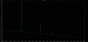
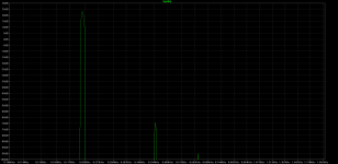
I simmed the Darius follower version and the gyrator loaded (no follower) version. Same input, FFT taken at 2A3 grid.
Although the Darius follower appears to generate a suprisingly high plate load for the input stage (very impressive actually), there's a significant difference in harmonic content as can be seen; about -20dB.
I also simmed with a 6 VAC component in the B+; the gyrator circuit seems to have about 55dB ripple rejection. I can't comment on whether this is good or not, since I always regulate B+.
I made some sims and formulated a response before realising that you were talking about the power stage while I was talking about the input stage. I myself use gyrator plate loads on all tubes, but most people think it's practical only in preamp stages so that's what I was thinking.
I'll first respond regarding input stage, then the power stage.
I simmed the Darius follower version and the gyrator loaded (no follower) version. Same input, FFT taken at 2A3 grid.
Although the Darius follower appears to generate a suprisingly high plate load for the input stage (very impressive actually), there's a significant difference in harmonic content as can be seen; about -20dB.
I also simmed with a 6 VAC component in the B+; the gyrator circuit seems to have about 55dB ripple rejection. I can't comment on whether this is good or not, since I always regulate B+.
Attachments
Decoupling again with these old bricks takes out the hated 'impressiveness' and brings back the appreciated 'speed'. It has more 'slam' than I remember, must be because of the worn GE tubes. Now setting for the target voltages, although... bias at -42/-44V and Uak at 240/237V is close
Although the circuit is considered constant current you experience that much difference in a couple of hundred ohm impedance? When experimenting I didn't like the single 15uF in the PS at all, doubling it seemed like a vane to the heart of the beast went open. Well, that's what it's all about, isn't it? do-it-yourself-audio (with a little help from friends).
GB: It's the effect of the NFB from 2A3 to the first triode I did not anticipate. Thanks for recalling to mind.
Outch, sounds pretty good now
An externally hosted image should be here but it was not working when we last tested it.
Although the circuit is considered constant current you experience that much difference in a couple of hundred ohm impedance? When experimenting I didn't like the single 15uF in the PS at all, doubling it seemed like a vane to the heart of the beast went open. Well, that's what it's all about, isn't it? do-it-yourself-audio (with a little help from friends).
GB: It's the effect of the NFB from 2A3 to the first triode I did not anticipate. Thanks for recalling to mind.
Outch, sounds pretty good now
Although the circuit is considered constant current you experience that much difference in a couple of hundred ohm impedance?
Not so much perhaps, but you see the difference in PSU II if serial resistance gets too high. For my first version, I had to add some serial resistance to the HT secondaries to tune the B+ voltage, and wanted to find a nice way to remove it. I had a few of these filament chokes and was always itching to try them out in a power supply.
Honestly though the PSU change with lower serial resistance *perhaps* makes it sound a *tiny tiny* bit better. It was already superb with the single LL 1673 choke.
Outch, sounds pretty good now
Excellent!

Regarding 2A3 plate loading:
The gyrator doesn't work against plate voltage swing at all.
In DC current; as much as you can dissipate in heat.
In AC signal current: about 80% of idle DC current times 2.
When plate voltage rises, the MOSFET needs to deliver more current to the load (OT). This charges the parafeed cap. When plate voltage falls, the parafeed cap must discharge, sending current down the tube. This makes the MOSFET conduct less current because current thru tube remains 'constant' at all plate voltages. Since we're looking at symmetric sine waves, the bottom sets the limit on the current swing here; the top MOSFET can conduct more current, but it can't conduct less than a certain amout. So it can swing 80% down, and the same amount up.
How do I get that number? Well, with the MOSFET on top, the whole totem pole acts as plate load (superior transconductance) and voltage amp (inferior transconductance). The MOSFETs transconductance is highly dependent on current though, so as it approaches 0mA cutoff, it's transconductance plummets. The closer the tube and FET are to each other in transconductance, the less the totem pole acts as voltage amp and plate load, and the more it acts as a (very bad) SRPP.
Distortion starts rising when the MOSFET gets closer to cutoff. Where the "starts to influence" sound quality point is, is a matter of debate. I'd say it's "super clean" up to 80% of max current swing.
So if your idle current is 60mA, that's what the tube sees all the time. The top MOSFET can swing from 12mA to 108mA while staying in super clean territory.
With B+ of about 425V and current of 60mA you'd dissipate about 10W on the plate load. That's pretty big. Less current would mean less dissipation.
With 425V B+, you'll be more than fine with regular 500V FETs.
Failure is almost always gate to source. This will drag plate voltage down; it won't damage the tube or OT.
Do you mean using damper diodes as rectification in the PSU? I've experimented with it only briefly.
Regarding slow start: I use the gyrators as my slow start. Use a big cap (I use K73 1.5µF / 160V as the plate to gate cap) and big R from the reference voltage (I use 3.3M usually), and it takes a few seconds for the plate voltage to rise. It's a delay circuit. In sims I usually make the cap much smaller for convenience (don't have to wait for it to charge).
Sounds promising. By holding that DC stable, does the Gyrator work against signal swing over my output tube plate at all?
The gyrator doesn't work against plate voltage swing at all.
How many mA's can a Gyrator reasonably manage before it starts to influence signal?
In DC current; as much as you can dissipate in heat.
In AC signal current: about 80% of idle DC current times 2.
When plate voltage rises, the MOSFET needs to deliver more current to the load (OT). This charges the parafeed cap. When plate voltage falls, the parafeed cap must discharge, sending current down the tube. This makes the MOSFET conduct less current because current thru tube remains 'constant' at all plate voltages. Since we're looking at symmetric sine waves, the bottom sets the limit on the current swing here; the top MOSFET can conduct more current, but it can't conduct less than a certain amout. So it can swing 80% down, and the same amount up.
How do I get that number? Well, with the MOSFET on top, the whole totem pole acts as plate load (superior transconductance) and voltage amp (inferior transconductance). The MOSFETs transconductance is highly dependent on current though, so as it approaches 0mA cutoff, it's transconductance plummets. The closer the tube and FET are to each other in transconductance, the less the totem pole acts as voltage amp and plate load, and the more it acts as a (very bad) SRPP.
Distortion starts rising when the MOSFET gets closer to cutoff. Where the "starts to influence" sound quality point is, is a matter of debate. I'd say it's "super clean" up to 80% of max current swing.
So if your idle current is 60mA, that's what the tube sees all the time. The top MOSFET can swing from 12mA to 108mA while staying in super clean territory.
How big would the gyrator heat sinks need to be for this amplifier (separate channels)?
With B+ of about 425V and current of 60mA you'd dissipate about 10W on the plate load. That's pretty big. Less current would mean less dissipation.
I know that MOSFET's need to be rated quite high to reduce chance of failure.
With 425V B+, you'll be more than fine with regular 500V FETs.
Not that failure is a bad thing, but what steps need to be taken to prevent further damage in case a Gyrator fails?
Failure is almost always gate to source. This will drag plate voltage down; it won't damage the tube or OT.
Do you ever use Gyrators with Damper Diodes? I like Damper Diodes especially for their very slow start. If you use Gyrator with silicon diodes, I think you must implement an effective slow start circuit as well. Don't you agree?
Do you mean using damper diodes as rectification in the PSU? I've experimented with it only briefly.
Regarding slow start: I use the gyrators as my slow start. Use a big cap (I use K73 1.5µF / 160V as the plate to gate cap) and big R from the reference voltage (I use 3.3M usually), and it takes a few seconds for the plate voltage to rise. It's a delay circuit. In sims I usually make the cap much smaller for convenience (don't have to wait for it to charge).
Curwen, thanks very much for your detailed answer!
I am thinking that the size of heat sink might be a bit much for this type of 2a3design... Maybe it would be possible for 45 tube... It should work for paralleled 4N1P
When I say slow start-up, I am thinking of at least 30 seconds.. I sometimes use a 1 min delay (after heater turn-on) on top of that.
Last edited:
- Status
- This old topic is closed. If you want to reopen this topic, contact a moderator using the "Report Post" button.
- Home
- Amplifiers
- Tubes / Valves
- My New Iron for Single Ended 2a3