After a small hiatus i'm back on track!
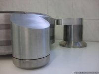
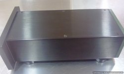
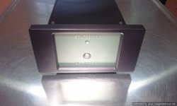
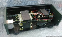
The new aluminum box for the two transformers and filtering board has arrived and i have decided not to use the original front and rear parts.
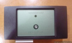
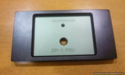
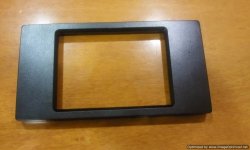
I have designed my own front part out of a 10 mm thick aluminum plate and the surrounding frame out of a 15 mm one.
It has openings for the on/off button and the led indication .
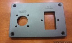
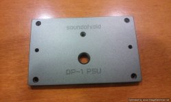
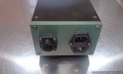
The rear was cut from a 10 mm one too and has the openings for the master power on/fuse/filter combo and the turntable umbilical receptacle.
On the front i have engraved my logo and the model name and on the back some info about power and umbilical in custom very modern fonts.
At the moment i am preparing them for painting in the same color as the turntable.
Olive green (front and back) and black frame.
See the pics.
The new aluminum box for the two transformers and filtering board has arrived and i have decided not to use the original front and rear parts.
I have designed my own front part out of a 10 mm thick aluminum plate and the surrounding frame out of a 15 mm one.
It has openings for the on/off button and the led indication .
The rear was cut from a 10 mm one too and has the openings for the master power on/fuse/filter combo and the turntable umbilical receptacle.
On the front i have engraved my logo and the model name and on the back some info about power and umbilical in custom very modern fonts.
At the moment i am preparing them for painting in the same color as the turntable.
Olive green (front and back) and black frame.
See the pics.
Attachments
-
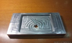 Photo0816-Optimized.jpg128.5 KB · Views: 342
 -
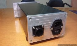 Photo0824-Optimized.jpg103.3 KB · Views: 67
 -
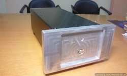 Photo0825-Optimized.jpg84.3 KB · Views: 57
 -
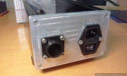 Photo0821-Optimized.jpg98.8 KB · Views: 59
 -
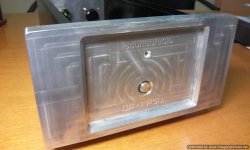 Photo0820-Optimized.jpg101 KB · Views: 318
 -
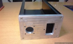 Photo0817-Optimized.jpg95.8 KB · Views: 322
 -
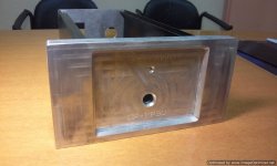 Photo0819-Optimized.jpg96.6 KB · Views: 321
 -
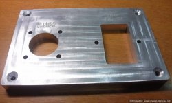 Photo0813-Optimized.jpg131.4 KB · Views: 330
I just got them back from the paint shop.
In BMW black and Nissan green just like the turntable chassis.
I have also "smoked" the silver button just like the silver buttons on the main chassis.
I'll wait for a couple days for the varnish to cure and i will start the assembly.
Looks good to my eyes...
In BMW black and Nissan green just like the turntable chassis.
I have also "smoked" the silver button just like the silver buttons on the main chassis.
I'll wait for a couple days for the varnish to cure and i will start the assembly.
Looks good to my eyes...
Attachments
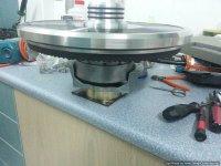
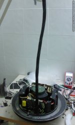
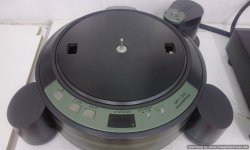
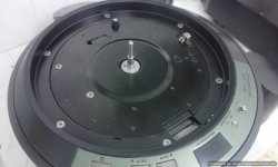
You remember the way it was configured with all the boards out...(first pic).
After hitting a brick wall with the magnetic head signal not being able to
sync properly when using a long cable loom, i had to return three of the boards inside the main chassis...
After a long thought and careful measurements i was able to place two boards back to back and free two spaces equidistant to the motor.
I placed there the silencer blocks nice and tidy.
Then i had to add some length to interconnecting cables between boards
and tidy up the cables around the chassis.
Another small mod was to make the fuse on the board accessible from the top so that you don't have to open the whole thing just for a fuse change.
With the new positioning you just lift the platter and the fuse is right in front of you.
I hooked up the the table to the parts that are going to be used in the power supply and fired away.
All went good for a change...!
Speed is tight and speed changes are crisp.
The new spindle needs to run some hours to settle in but it's already dead quiet even without the damping of the massive exoskeleton...
All i have to do now is tidy things up and bolt it all together...
Phew....!
Attachments
-
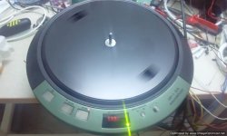 Photo0855-Optimized.jpg81.6 KB · Views: 125
 -
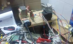 Photo0856-Optimized.jpg105.4 KB · Views: 107
 -
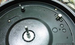 Photo0857-Optimized.jpg165 KB · Views: 95
 -
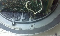 Photo0853-Optimized.jpg95.8 KB · Views: 113
 -
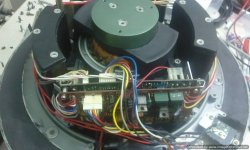 Photo0850-Optimized.jpg102.8 KB · Views: 119
 -
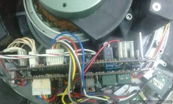 Photo0851-Optimized.jpg135.1 KB · Views: 120
 -
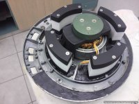 Photo0706-Optimized.jpg100.3 KB · Views: 126
Glad you like it Theophile!
The plinth is ready ages ago!
It was waiting for the damn electronics to decide to work properly!
In case you missed it ...see some pics.
As for the supporting table...i have no control.
I will advise the owner about what i would want to see but i suspect that it's cost will be prohibiting.
You need a lot of magnets to raise 100Kgs...
If he wants another route i have made a very sturdy one
with three tiers to support table ( a Kuzma XL-2), a TLA phono stage and power supplies. I will find a photo of it and i will post it...
Attachments

I don't necessarily think that mag-lev is the key requirement. I truly think that the key requirement is a circular arrangement of some kind of spring with the turntable placed within the circle of equally spaced springs, in such a manner that the center of gravity of the turntable is located to be equidistant from each of the springs. The mass would need to be optimised for the multiple springs.
That is what I have been working towards for number of years now. Using in my case the Clearaudio Magix, but I have a hunch that the same would apply with ordinary springs. I have made things difficult for myself by complicating the entire thing with a ball and cup set-up on the platform atop the circular spring(Magix) arrangement. I doubt that I have even optimised the whole thing yet, but the results of getting closer all the time only reinforce my resolve to get the most out of this method.
I simply could not do without the improvement that I have experienced.
The owner is an audio dealer in Hong Kong and i don't know where he is going to place it in his demo room.
He is also a dealer of ASI (Acoustic System International) products so he must know a thing or two about taking care of vibrations...
I see multiple manufacturers of isolation products who are not applying this idea. It stands to reason that unless the spring or compliant module is loaded with the same weight, it is isolating at a different frequency to it's neighbour. The frequency of the isolation depends upon the compliance of the isolator versus the mass being isolated. Thus if the center of gravity of the load is not shared equally each compliant isolator module(spring/magix/ isomer) is isolating at a different frequency and the entire platform is leaking through frequencies due to the spread of the frequencies.
In other words: They aren't doing it right.
I guess the problem is that when you are making a generic product about isolation
you don't actually know where it is going to be used.
It takes some hard work on the end user to establish the absolute center of mass
of the component he or she wants to isolate.
And when things weigh a severe amount of kilos it gets pretty difficult to manipulate the damn thing..!
you don't actually know where it is going to be used.
It takes some hard work on the end user to establish the absolute center of mass
of the component he or she wants to isolate.
And when things weigh a severe amount of kilos it gets pretty difficult to manipulate the damn thing..!
I guess the problem is that when you are making a generic product about isolation
you don't actually know where it is going to be used.
It takes some hard work on the end user to establish the absolute center of mass
of the component he or she wants to isolate.
And when things weigh a severe amount of kilos it gets pretty difficult to manipulate the damn thing..!
Absolutely I agree. The point is they are a sham. The difference when you tailor the solution to fit the problem is that you get a solution to the problem. What that does for turntable performance has to be heard to be believed. It takes a great turntable to another level altogether.
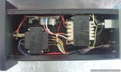
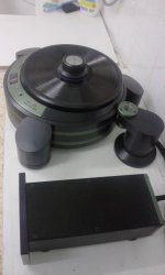
After three days of intensive (last night i was working even after midnight on it) work the power supply is ready.
It is more packed than i imagined but not too packed.
It all fitted in a 14cm X 33cm aluminum box...about 6 kilos.
I did my best on fit and finish...inside and out.
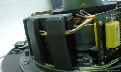
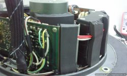
I have added damping sheets on all panels and spaced the transformers wide enough.
It was the first time i used a gold pin TE twist-lock receptacle and i was a bit worried but it ended OK.
See some pics...
It is more packed than i imagined but not too packed.
It all fitted in a 14cm X 33cm aluminum box...about 6 kilos.
I did my best on fit and finish...inside and out.
I have added damping sheets on all panels and spaced the transformers wide enough.
It was the first time i used a gold pin TE twist-lock receptacle and i was a bit worried but it ended OK.
See some pics...
Attachments

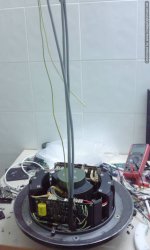
Today is the day i start on the umbilical.
It's 12 contacts grouped into 3 cables that are shielded plus one chassis ground...i hope i kept good notes!
I payed special attention in securing them before exiting the chassis.
You never know when someone is going to pull the whole thing from the umbilical!
Then all wrapped together nice and tidy.
In contrast to my working area....
Attachments
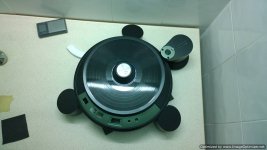
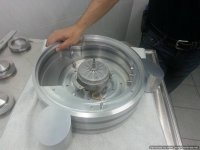
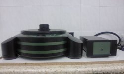
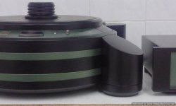
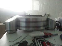
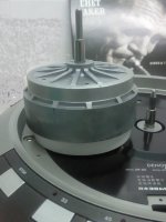
First time with a test fitting!
It was very difficult to "sink" the motor part into the chassis without damaging the paint.
Thank God for the foamy inserts around the hollow part of the chassis that made things gradual and controllable.
It fitted snugly and was screwed down with countersunk screws.
The new (black too) platter ,extra metal mat and periphery ring are made to exact measure.
I am very happy with the solidity, damping, fit and finish of the whole thing.
It is more than 80 kilos in total.
It will be a major project to ship it safely....
Attachments
First time with a test fitting!
It was very difficult to "sink" the motor part into the chassis without damaging the paint.
Thank God for the foamy inserts around the hollow part of the chassis that made things gradual and controllable.
It fitted snugly and was screwed down with countersunk screws.
The new (black too) platter ,extra metal mat and periphery ring are made to exact measure.
I am very happy with the solidity, damping, fit and finish of the whole thing.
It is more than 80 kilos in total.
It will be a major project to ship it safely....
Congratulations on a terrific realization of a great design. Just the right amount of understatement combined with a dramatic eye catching shape. Classy. Visually, this one really works for me.
-Steve
Thank you Steve!
I really pushed hard on this one...and i've learned a bunch of things...the hard way!
The basic idea was there from my previous efforts but i kicked it up a couple notches with this one.
Aesthetics played a major part.
I tried to make everything look good together.
There are a thousand things to look after when you aim for an eye pleasing design.
The way the slopes intergrade, the hiding of the screws, the color blend so that it does not show "too much", to fit so many parts together...
And you have to make all this while keeping the mechanics proper so that you don't sacrifice the performance.
The good thing is that with each step you go, your eye sees even more potential and you are ready for the next -better- one.
I have already made my designs for the next one.
Only the motor (modified) and lower platter will be kept from the DP.
Even the main chassis holding the motor will be cut from solid.
All the electronics with new boards will be moved into a full blown PS/control box.
This will have to be right under the turntable to control it.
I have solved the problem of electronic sync with the magnetic head.
I will cut a super hard carbide axle two mm thicker, longer self lubricated bronze bushings and will definately use magnetic levitation
while keeping the direct drive scheme...a world first.
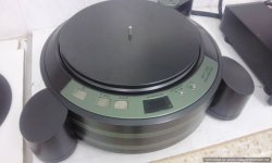
No buttons on the turntable...just the strobo screen.
I only need sponsoring for this...anyone out there?
First one will get it at pure cost...!
From now on i will post some of the pics throughout all this that show the details i like the most...
I really pushed hard on this one...and i've learned a bunch of things...the hard way!
The basic idea was there from my previous efforts but i kicked it up a couple notches with this one.
Aesthetics played a major part.
I tried to make everything look good together.
There are a thousand things to look after when you aim for an eye pleasing design.
The way the slopes intergrade, the hiding of the screws, the color blend so that it does not show "too much", to fit so many parts together...
And you have to make all this while keeping the mechanics proper so that you don't sacrifice the performance.
The good thing is that with each step you go, your eye sees even more potential and you are ready for the next -better- one.
I have already made my designs for the next one.
Only the motor (modified) and lower platter will be kept from the DP.
Even the main chassis holding the motor will be cut from solid.
All the electronics with new boards will be moved into a full blown PS/control box.
This will have to be right under the turntable to control it.
I have solved the problem of electronic sync with the magnetic head.
I will cut a super hard carbide axle two mm thicker, longer self lubricated bronze bushings and will definately use magnetic levitation
while keeping the direct drive scheme...a world first.
No buttons on the turntable...just the strobo screen.
I only need sponsoring for this...anyone out there?
First one will get it at pure cost...!
From now on i will post some of the pics throughout all this that show the details i like the most...
Attachments
-
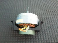 Photo0681-Optimized.jpg109 KB · Views: 98
 -
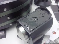 Photo0614-Optimized.jpg76.5 KB · Views: 88
 -
 Photo0850-Optimized.jpg102.8 KB · Views: 83
 -
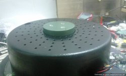 Photo0849-Optimized.jpg84 KB · Views: 78
 -
 Photo0449-Optimized.jpg59.8 KB · Views: 87
 -
 Photo0484-Optimized.jpg60.3 KB · Views: 93
 -
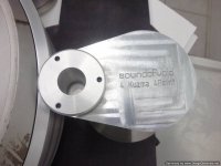 Photo0416-Optimized.jpg77.1 KB · Views: 72
 -
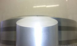 Photo0397-Optimized.jpg48.8 KB · Views: 81
 -
 20140207_205258-Optimized-1.jpg150 KB · Views: 97
 -
 20131107_122821-Optimized.jpg107.1 KB · Views: 115
And some more...
I'll have to buy a separate hard drive to keep them safe...
I'll have to buy a separate hard drive to keep them safe...
Attachments
-
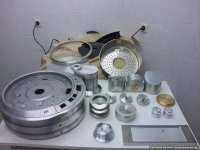 Photo0507-Optimized.jpg97.2 KB · Views: 94
 -
 Photo0435-Optimized.jpg57.5 KB · Views: 90
 -
 new spindle 1.JPG50.4 KB · Views: 79
 -
 Photo0824-Optimized.jpg103.3 KB · Views: 69
 -
 Photo0786-Optimized.jpg77.8 KB · Views: 80
 -
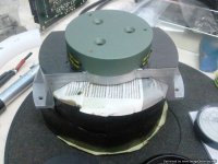 Photo0632-Optimized.jpg115.8 KB · Views: 99
 -
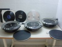 Photo0538-Optimized.jpg78.5 KB · Views: 106
I have already made my designs for the next one.Only the motor (modified) and lower platter will be kept from the DP.
Even the main chassis holding the motor will be cut from solid.
All the electronics with new boards will be moved into a full blown PS/control box.
I look forward to seeing a rearrangement of placing the motor & platter onto a completely different plinth and separate electronics enclosure. I think that's the way to do it whole hog style, ie, ditching the stock spaceship chassis. I honestly think too many direct drive tables are cluttered with electronics and unnecessary mechanism. I like seeing the plinth as simple as possible and placing all the complicated electronics into a separate box. The Monaco Grand Prix is one example. The Brinkmann Bardo is another elegant design.
By the way, your work is superb and, dare I say, obsessive.
Thanks, I AM obsessed.
It will be with a custom longer spindle cut from carbide, about 2mm thicker, that will permit the use of magnetic repulsion.
All the power and torque of this gigantic motor, over 10kgs platter with zero drag.
Only the motor inside the chassis, all the electronics out in new boards.
Custom power supply with modern soft touch switches...the works.
But...i do like the round shape!
What i was aiming, was to take all electronics out of the main chassis.
It didn't happen at this phase as i was not able to sync properly the signal from the magnetic head with the outboard electronics.
The 1.5 meters umbilical was degrading the signal up to the point that the lock was unstable.
I have my electronics wizzard look into it and it is now a solved problem.
We are expecting some parts to arrive to make our final tests and calibration
so that will soon be a problem of the past.
As it is, we have beefed up the transformers, added extra filtering, used bypass caps at crucial points on the circuit and replaced some of the power transistors with newer more robust versions.
In the next one we are going to use new boards, new thicker CNC cut top chassis and top platter section and a full blown external PS/control box that will have all the buttons on it's fascia...only the stroboscope screen will remain on the top chassis.The motor axle will be thicker (cut from carbide) and longer so that it will accomodate a ring magnet to have magnetic levitation.From the original Denon only the motor and lower platter will be used.
Merry Christmas everybody!
- Status
- This old topic is closed. If you want to reopen this topic, contact a moderator using the "Report Post" button.
- Home
- Source & Line
- Analogue Source
- My new effort on making the ultimate DP-80