It's the difference that feedback makes in trying to reduce distortion until finally it can't and the distortion due to the onset of clipping skyrockets.
Causality is the other way around. At the onset of clipping, the loop gain collapses and there is effectively no more feedback available to correct the distortions.
That's an odd way of saying you agree that the distortion skyrockets !Causality is the other way around.
At the onset of clipping, the loop gain collapses and there is effectively no more feedback available to correct the distortions.
Glad to see this resurface. I think this will be my next build, maybe with two pairs of output FETs running off +/-58V rails.
Some years back I built an amp based on the Nytech/Ion topology, which uses a singleton input. It was one of my favourites, just seemed to sound right. I have no idea why I dismantled it
Some years back I built an amp based on the Nytech/Ion topology, which uses a singleton input. It was one of my favourites, just seemed to sound right. I have no idea why I dismantled it
Hi Mooly!
I'm planning to build your designs and I have questions regarding the pre-amp implementation. Could you please explain in details how you implement the input of the pre-amp? I'm not clear about the volume control and how you drive the JFET switches.
I would also like to find out the wisdom behind the equal gain distribution between the OPA604. Have you compared current setup with a setup where the last op-amp is a buffer?
TIA
Attachments
The volume control was a motorised ALPS 10k pot located after the second opamp. The opamp arrangement was mainly to correct for absolute phase, and the 22k/18k ratio was decided on to give a little gain on each stage although in practice very little if any gain is needed with the power amp having high sensitivity. Subjectively it all feels 'right' regarding rotation of the volume control and perceived levels.
Having settled on that arrangement I never felt inclined to alter it tbh.
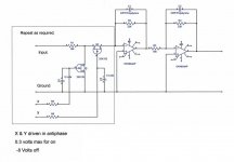
The FET's need to be driven with assymetric logic levels, logic 1 being around 150mv and logic 0 being minus 8 volts. When one FET is on, the other is off.
Limiting the positive drive voltage to 150mv ensures the FET gate channel does not begin to conduct which would add a DC offset. Also using 150mv rather than 0 volts ensures the FET is fully turned on, that little voltage above 0 volts makes a big difference to the on resistance achievable with the FET's. I used germanium diodes as clamps in the original version and they have worked well.
The minus 8 volts level is pretty arbitrary but it does ensure that no conceivable signal applied to the inputs can break through when that input is deselected. I used a PIC to control the input selection together with a discrete logic (CMOS 4000 series) decoder to drive the four line input switching FET's.
It would be easy to rig up manual switching for the FET's from a rotary switch if needed.
Having settled on that arrangement I never felt inclined to alter it tbh.
The FET's need to be driven with assymetric logic levels, logic 1 being around 150mv and logic 0 being minus 8 volts. When one FET is on, the other is off.
Limiting the positive drive voltage to 150mv ensures the FET gate channel does not begin to conduct which would add a DC offset. Also using 150mv rather than 0 volts ensures the FET is fully turned on, that little voltage above 0 volts makes a big difference to the on resistance achievable with the FET's. I used germanium diodes as clamps in the original version and they have worked well.
The minus 8 volts level is pretty arbitrary but it does ensure that no conceivable signal applied to the inputs can break through when that input is deselected. I used a PIC to control the input selection together with a discrete logic (CMOS 4000 series) decoder to drive the four line input switching FET's.
It would be easy to rig up manual switching for the FET's from a rotary switch if needed.
The volume control was a motorised ALPS 10k pot located after the second opamp.
Ah! that clarifies things (The pot is not shown on the pic). The amplifier input impedance is less than 47k. I think common standard is to drive such load with source impedance of at least 1/10 times 47k, hence 4k7. I think this is the reason why I found out that not only that 10k pot is insufficient but a buffer is a must in front of any power amplifiers.
I used a PIC to control the input selection together with a discrete logic (CMOS 4000 series) decoder to drive the four line input switching FET's.
It would be easy to rig up manual switching for the FET's from a rotary switch if needed.
Yes, I think I can figure it out, tho I have forgotten the tricks with working with the IC switches. Right now I cannot visualize and compare its complexity versus the standard relay input switch.
Thank you, Mooly!
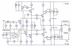
I wouldn't advise SMD for Q3 and Q5 as they will be dissipating around 300mw. That is to close to the max 350mw rating of the SMD package. It would also require extreme care with the thermal management of those two devices to ensure they could be kept cool. The others should be fine, just not those two.
R26, yes, and that is because it in part helps define the character of the amp by slightly increasing real world damping factor, and it also helps prevent RF ingress into the main feedback node caused by speaker cable pickup.
R23 and R24 almost certainly could be removed and I wouldn't foresee any practical issues doing so... but it would be an untested modification and so unproven as to the final results.
R23 and R24 almost certainly could be removed and I wouldn't foresee any practical issues doing so... but it would be an untested modification and so unproven as to the final results.
I wouldn't advise SMD for Q3 and Q5 as they will be dissipating around 300mw. That is to close to the max 350mw rating of the SMD package. It would also require extreme care with the thermal management of those two devices to ensure they could be kept cool. The others should be fine, just not those two.
There is an SOT223 package for 5401/5551 that can dissipate more power.
DZT5401 (1W):
https://www.diodes.com/assets/Datasheets/DZT5401.pdf
DZT5551 (2W):
https://www.diodes.com/assets/Datasheets/ds31219.pdf
I have used these before and they work well.
The series 0.22 ohm should be a 3watt rating for worst case sine power testing. On -/+45 volts rails into 8 ohm loading it will see around 3.25 A (rms) which is a dissipation of 2.3 watts. The source resistors see only around half that averaged over time although in both cases the peak currents are around 4.5 amps.
Anything other than full power testing under sine conditions and 2 watts would be OK.
I used these Welwyn types:
http://cpc.farnell.com/welwyn/w21-0r22-ji/resistor-ww-3w-5-0r22/dp/RE04656?st=0.22 ohm
Anything other than full power testing under sine conditions and 2 watts would be OK.
I used these Welwyn types:
http://cpc.farnell.com/welwyn/w21-0r22-ji/resistor-ww-3w-5-0r22/dp/RE04656?st=0.22 ohm
I now have a pair of MMADFMs working nicely on my test bench, running off +/-36V rails.
Bias stability is fine, set at about 100mA for the single output pairs. This will increase slightly when running off 40V rails in the actual amp.
Reactive load transient response looks nice, indicating good stability margins. Although the 0.22R in the output will help here.
As Mooly said, there are voltage transients at turn on and turn off. So when it gets built into an actual amplifier I have provisioned for dc offset protection and a slow-on fast-off circuit.
Looking forward to hearing it!
need boards and boms
Mooly your amplifier is one i would like to try sometime. it would make life little easier if someone made up boards and boms so we can just order and build
a few questions if you will...output power? distortion? and finally what is there to be gained by your design over others including my beloved HK430
Lawrence
that's great. I hope you enjoy it as much as I have with mine.
Mooly your amplifier is one i would like to try sometime. it would make life little easier if someone made up boards and boms so we can just order and build
a few questions if you will...output power? distortion? and finally what is there to be gained by your design over others including my beloved HK430
Lawrence
- Home
- Amplifiers
- Solid State
- My MOSFET amplifier designed for music