The easy plug-n-play solution is MJL21194, so you can nicely upgrade the linearity without the inconvenience of readjusting the amplifier.Do we need this big output transistors for 11W?
The NJW3281G are excellent devices, currently in production and big enough for this. Actually i'm thinking of something even smaller (but that i could find matched). Among the monolithics, there is something suitable with power dissipation?
If I interpret correctly, NJW3281G works fine but the amplifier will not exploit the speed of the device, unless the amplifier is readjusted to support a specific fast device.I also noticed that on my prototype, the 47n C14 was left in place as in V5d. This probably helps. When the amp is pushed into clipping, a VHF oscillation is visible with the faster types, but nothing dangerous or alarming. This means that the new Onsemi types should work transparently.
I have no memory of such an effect.... Forgotten maybe?minimizing memory distortion (if you believe that thay exist)
No, certainly not: the dissipation/transistor is moderate, ~25W but permanent.Do we need this big output transistors for 11W?
A big heatsink is required anyway, the size of the transistors does not matter
They are overkill: even devices having a Pc max of 60W would be sufficient.The NJW3281G are excellent devices, currently in production and big enough for this. Actually i'm thinking of something even smaller (but that i could find matched).
Note that the power devices do not really need to be matched: if you are going to match something, it has to be the drivers. That's the beauty of the CFP.
That is true: some tweaking of the stabilization could unleash their full potentialIf I interpret correctly, NJW3281G works fine but the amplifier will not exploit the speed of the device, unless the amplifier is readjusted to support a specific fast device.
They are overkill: even devices having a Pc max of 60W would be sufficient.
Note that the power devices do not really need to be matched: if you are going to match something, it has to be the drivers. That's the beauty of the CFP.
Didn't you say that M1 and M2 needed to be matched at best possible?
Yes, but that applies to the complete composite transistor, and only the driver has a significant impact on the global parameters (within reason)Didn't you say that M1 and M2 needed to be matched at best possible?
Now, you are free to match the power devices too, it will only be better, but if you don't match the drivers first, it will be completely useless.
Last edited:
The MJL21194's that I received from OnSemi can be poked into the DMM HFE test port. All of them were fairly close to match. Unfortunately the DMM test port with low current and room temp wasn't realistic test conditions.
Operating conditions question: The Drivers are rated 0.6w without heatsink or 3w with heatsink. Do they need heatsinks? If so, then may I infer that my DMM HFE test port could be inadequate?
Operating conditions question: The Drivers are rated 0.6w without heatsink or 3w with heatsink. Do they need heatsinks? If so, then may I infer that my DMM HFE test port could be inadequate?
THey dissipate typically less than 0.3W, so they need no heatsink.Operating conditions question: The Drivers are rated 0.6w without heatsink or 3w with heatsink. Do they need heatsinks? If so, then may I infer that my DMM HFE test port could be inadequate?
Matching by Hfe is a relatively poor method. With a multimeter, there is a much more accurate one: in the "diode test" mode, measure the B-E voltage, first with C left open, then with B and C connected.
This couple of values is the "signature" of the transistor, and if you find two having the same, they will be a very good match.
The absolute temperature is unimportant, even if they will be operated at a much higher one. But keeping all the transistors at the same temperature during the measurements is essential.
A good way of achieving this is to plug all the TUTs into a breaboard, with the emitter in common and two wires for B and C. You cover the whole with some kind of box, tupperware or equivalent, leave them equalize their temperature for 5 minutes and then make the measurements.
Since it is a no-feedback amp, it requires no compensation (one could argue about the input/VAS, but since it is a single stage it is irrelevant), and the distinction doesn't apply.Is Tringlophone a shunt comp amp capable of a bit of dynamics expansion (sounds live) like the Circlophone can do?
The stabilization networks are shunt, but their effect is tiny compared to the compensation of a "normal" amp: they do not alter the "natural" behaviour of the amplifier.
Have you seen Counter culture's layout?Anyone making boards for this project?
http://www.diyaudio.com/forums/solid-state/221309-my-little-posh-tringlophone-4.html#post3208143
Excessive capacitance can degrade the performances, but all feedback amplifiers require some compensation.Any capacitance added increase distortion. You have not this trouble in this amplifier here.
Properly applied capacitance makes these amplifiers possible.
The gain is set by the ratio of the 330R and 3K9, in this case 21.5dB.My computer definitely has trouble pushing an 11w amp with 26db gain. What gain does Tringlophone have?
If you find it too low you can decrease the 330R, but R25 should follow R23 to keep the bias correct. Some tweaking might be required to retain the maximum dynamic, as the system works open loop
Elvee
I have ~10 pcs of KD502 and KD503 transistors http://www.elenota.pl/datasheet-thumbs/big/KD502_datasheet_125964_0.png
can I use them directly instead of 2N3055?
I have ~10 pcs of KD502 and KD503 transistors http://www.elenota.pl/datasheet-thumbs/big/KD502_datasheet_125964_0.png
can I use them directly instead of 2N3055?
They look perfectElvee
I have ~10 pcs of KD502 and KD503 transistors http://www.elenota.pl/datasheet-thumbs/big/KD502_datasheet_125964_0.png
can I use them directly instead of 2N3055?
You are free to use darlingtons instead: the circuit will work almost identically, but with less headroom and a reduced linearity, but nothing really alarming.
And such a circuit will certainly be more placid.
Elvee, could you provide at least a sketch to show how manipulate NPN darlingtons on the original schematic?
It seems my to-do list will rise again by following your "little" designs. I like the way of your using big and small metal case transistors everywhere.. I like the oldskool fashion
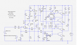
Here is the adapted version, tested in sim only (but it should be more placid than the CFP).
As expected, it has less swing and linearity, but nothing catastrophic.
Thank you very much Elvee. I felt a bit ashamed by seeing redrawn of whole schematic. Your kindness as usual.
If different type of transistors were used (original or darlington), can you elaborate that which parts of the circuit going to be considered for fine tuning? I'm sorry but I can't read the circuits like many people here.
At last, I bought an analogue 20mhz oscilloscope. Remarkable improvement for an electronics hobbyist. I expect that I could do some fine tuning on my builds but my theoretical base is at very early stage. I hope to improve my skills in time.
First, you could look at the differences between this schematic and the regular one, beyond the simple sex-change: there are many, some quite subtle.If different type of transistors were used (original or darlington), can you elaborate that which parts of the circuit going to be considered for fine tuning?
There is certainly still place for refinement on those departments.
Then you can test the effect of different values in the stabilization networks.
I'm collecting parts of Tringlophone and some questions become to consider somehow.
For Q13, is Vce critical? Is higher Hfe preferable?
For 2N2905A's.. In case of mixing different brand/ranking transistors, can we group 2905A's ? If so, which ones is not critical in terms of Hfe? I mean can we use somewhere 2N2904 (Reduced Hfe version of 2905) without any side effect?
Same for 2N2219A's.. Can we group these ones, or is it beneficial to use same rank transistors everywhere?
- Status
- This old topic is closed. If you want to reopen this topic, contact a moderator using the "Report Post" button.
- Home
- Amplifiers
- Solid State
- ♫♪--My little posh Tringlophone--♪♫