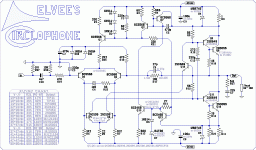
No problem, but you have to understand that derating indiscriminately at every component of the amp can only bring trouble. Derating makes sense for heavily stressed components, typically OP devices. . . . No resistor risk overheating, even at total supplies in excess of 120V. The 250mW rating remains adequate in all cases, though I would advise a larger rating for R17, in the interest of linearity.
The derating spree has a cause. I had changed the feedback resistor to 22k (albeit 20k is fine), and that higher gain has necessarily more energetic dynamics. Do I still need a 1/2w resistor or is 1/4w fine? Most computers and mp3 players distort, compress, blare or even clip slightly if run at max; and, Rightmark audio analyzer can confirm that on a case by case basis. So, really more pleasant playback was the reason that I changed the resistor. It works nicely. But, it works better than expected. It is like removing shackles and like trading a mouse for a tiger. That is worth an interview.
Probably, the 6db more from the speaker difference between my 45w amp versus a 150w amp, should not require a large increase of gain to facilitate that difference. I do not know, but it seems that we could decrease the 470R very slightly and perhaps use matched BC560C at input to enhance capacity for gain?
(not shown) A version of Ken's soft clip device, replacing R16, with 325R,145R divider (plus, in real application, to decrease current, an additional 470R between "wiper" and diodes) does seem to work quite well and is worth an interview. It seems especially suited to a high gain amp (integrated amp), to help constrain momentary conditions.
(not shown) I also added ---|<---->|--- zener stopper parallel with the 10k input load. This is extremely helpful. It doesn't do much for most of the time, but sometimes it blocks crazy (source selector dial and/or computer startup, power saver cycling) and it does its job well. It is capacitive and blocks RF too. That is also worth an interview.
The schematic in post 1 is really great, but documentation has more questions to answer. Parts availability and easier shopping is the primary motivation of the schematic below. It is easier to read than pagefulls of posts. I hope the D7 and R21 sections are suitable? If the power amp schematic below is okay, then I could proceed to page 2 of the documentation for Circlophone options and accessories. For the second page (accessories and options) it seems really nice to start out with jfet buffer accessory if that is doable?
Attachments
Last edited:
150W is ~35V rms. If you want 200mV nominal sensitivity (that's 175mV including some margins and tolerance), you need a gain of 200.Maybe I don't need 200x? So, I have 22k feedback resistor on a 45w to 8R amplifier and for 75w to 8R, that doesn't need much more gain. So, is there a suitable way to do just a little bit more, like maybe some fine tuning or an especially suited device selection?
You can have some excess gain and leave the volume control half-way. That's no rocket science, there is no influence on "dynamics" or temperature or anything: controlling the overall gain by whatever method yields identical results (within reason obviously).
No, this is completely irrelevant: what you see are variations caused by secondary effects, mainly Early effect on the OP transistors and the finite loop gain of the common mode mode servo.Together with common mode feedback, one emitter must be at constant current.
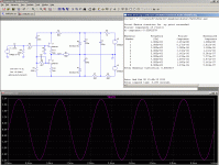
Simulation confirms this. Effective emitter resistance is, pluggin' numbers from
the graph into my calc. Taking out the tilt and going by the hump in the middle.
Converting those variations into resistance is meaningless.
In fact, both transistors are affected by the "logic" as you call it: the "constant curent" one obviously, as you noted, but the other too: simply, the correction has the same phase as the noble signal and the result is to double the amplitude of the variation.oh about 1.1K??? R1 clearly becomes significant to the differential by way of the
other emitter. The other one, not jammed to constant current by a logic threshold,
maybe a few ohms per your numbers.
You have two signal superposing there: the regular, differential, that would normally cause equal and opposite variations in the transistors, like any other LTP, and the common mode signal which reinforces whichever side is "positive", and cancels the other: the bias is continuously sliding, twice per cycle.
You can see this waveform in R1's current for instance.
R1 has very little effect on the differential mode: it simply form a Tee attenuator with the two re's of the transistors, but since at that current, the re's are much smaller, the effect is very small. In addition, the drive is balanced, which further contributes to eliminate any effect.
But on the contrary, R1 directly dictates the common mode gain (transconductance).
Making it 0 is not impossible, but it would make one's life very difficult, because the common mode gain is already more than sufficient, and increasing it unreasonably would require very good compensation.
There is no point going round and round that issue, given the price difference between 0.25 and 0.5W. Simply use 1/2 or even 1watt, good quality, that's all.The derating spree has a cause. I had changed the feedback resistor to 22k (albeit 20k is fine), and that higher gain has necessarily more energetic dynamics. Do I still need a 1/2w resistor or is 1/4w fine?
Looks OKIf the power amp schematic below is okay,
Last edited:
I apologize for asking, are BAT85 (30V) and BAT47(20V) suitable for D7 with 31V supplies? Does D7 share Vs or 2xVs with 1N4148 or regardless with Vs? My working setup is on the shelf by now and I can't measure voltages just for a while.
I found NOS 2N5858's at a local supplier and bought 10 of them.
I found NOS 2N5858's at a local supplier and bought 10 of them.
Last edited:
Does D7 share Vs or 2xVs with 1N4148 or regardless with Vs?
You can assume that this part is not exist.
Both are suitable.I apologize for asking, are BAT85 (30V) and BAT47(20V)
None of the diodes in this amplifier has any reverse voltage applied (except for the zeners, of course).
matched BC560C at input to enhance capacity for gain?
Using high gain transistors does not actually change the gain of the amplifier.
I think I see more or less what you mean: the bias servo system creates a structural gain increase of 6dB compared to a non-servoed stage, but this has nothing to do directly with R1, and the 6dB gain supplement doesn't depend on its value.Voltage decided entirely by R1 and opposite emitter.
R1 would be degenerating "differential" gain, because
it is ping-pong single ended half cycle for all practical
purpose... Very little common mode about it.
In fact, this could be compared to the functioning of a parametric amplifier (it is one actually): one parameter of the amplifier is modulated at twice the rate of the carrier by a pump frequency.
The pump frequency does not directly contribute to the output, and if it is applied alone, no output signal is generated.
Here, the pump signal is generated by the common mode loop.
In order to keep the normally inactive half of the amplifier at the threshold of activity, the general operating level is raised, which results in a doubling of the amplitude for the active part.
In a conventional amplifier, the inactive half goes into deep cut-off, and does not contribute to the output, because transistors are unidirectional devices, and can only source or sink current.
It is because of this diode-like non-linearity that the pumping process can take place and provide gain: in a pure class A amplifier, it would simply modulate the standing current, but would not provide any supplement of gain.
The modulation reinforces the action of each active half in turn.
For this effect to happen, one must have a means of modulating the current: here, it is the common-mode voltage combined with R1, but it could as well be a CCS controlled by the bias servo; that is an alternative method to create a Circlophone.
Here, the parametric amplifier mechanism is not the main purpose, it is just a side effect of the servoing method.
Using high gain transistors does not actually change the gain of the amplifier.
I think Daniel means that could we get similar affect like Elvee's new CFP implementation if using aka 700 Hfe LTP transistors rather than 250 Hfe ones. I may wrong but it sounded like me that.
Generally those super high betas come in NPN flavor only.
But worse to invert the whole circuit and make output PNP.
You can drop or add a stage, to make in and out both NPN.
I think this guarantees a detriment to either gain or stabilty.
The existing compromise is pretty good, but you can always
mess it up if you dare.
But worse to invert the whole circuit and make output PNP.
You can drop or add a stage, to make in and out both NPN.
I think this guarantees a detriment to either gain or stabilty.
The existing compromise is pretty good, but you can always
mess it up if you dare.
Input: The input resistance is approximately 10K. But, the source impedance must be kept well below that value. This is because the tail current of the input pair is dynamically modulated by the bias servo, and any imbalance in the input impedance will generate a parasitic voltage due to the bias currents of the input transistors. This will cause a "leak" of the common mode signal into the "noble" differential path, and will increase the distortion. For this reason, source impedance much greater than 1K should be avoided.
. . .A jFET buffer can certainly be added. . .
Thank you! That is a great idea, but I need some help with it.
The added jfet buffer is one way that I could ensure that the amplifier performance remains more likely constant between sources and not have me unnecessarily troubleshooting for a very long time like a puppy chasing its tail until dizzy. Help! How do I install this jfet? Could you provide a schematic example of how to install the jfet to the Circlophone at post 1?
I believe that the added part will help promote reliably repeatable results as well as greater compatibility to various sources of which there is vast variety. And, that variety needs tamed a bit. Jfet buffer?
P.S.
At that point, the very next question would be ideal specs for jfet shopping.
Something like the Pass B1 would be suitable:Thank you! That is a great idea, but I need some help with it.
The added jfet buffer is one way that I could ensure that the amplifier performance remains more likely constant between sources and not have me unnecessarily troubleshooting for a very long time like a puppy chasing its tail until dizzy. Help! How do I install this jfet? Could you provide a schematic example of how to install the jfet to the Circlophone at post 1?
I believe that the added part will help promote reliably repeatable results as well as greater compatibility to various sources of which there is vast variety. And, that variety needs tamed a bit. Jfet buffer?
P.S.
At that point, the very next question would be ideal specs for jfet shopping.
www.passdiy.com/pdf/B1 Buffer Preamp.pdf
I may have something cleverer in my "organ bank", I'll make some searching.
Maybe sort of like an inbuilt something? Like a streamlined, matching, piece of the amplifier rather than a whole different add-on unit?
What about an op amp buffer? You could give it some gain if you wish, and drive it from zenered or regulated supplies from the main amplifier supply depending how high it is. This would provide very low output impedance and solve your problem very simply.
Maybe sort of like an inbuilt something? Like a streamlined, matching, piece of the amplifier rather than a whole different add-on unit?
good idea.....
Maybe sort of like an inbuilt something? Like a streamlined, matching, piece of the amplifier rather than a whole different add-on unit?
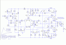
Here is a suitable buffer to match the Circlophone, clever enough not to degrade its performances:
Attachments
I will try it, one of these days.Anyone building CFP Circlophone ?
Inserting Q7 and Q8 in the LTP should be possible cleanly, with a bit of reflection.It seems it is not that easy to graphically modify current pcbs respecting cfp modifications.
The mod in the feedback cap can be wired "in the air".
Reversed? What do you mean?RC zobel at output reversed in CFP version.. misprint?
Reversed? What do you mean?
5R6 and 22nF.. 5R6 is connected to output at original but it is connected to ground at CFP. Vice versa for 22nF.
- Home
- Amplifiers
- Solid State
- ♫♪ My little cheap Circlophone© ♫♪


