Good work. In my opinion selection of C5 330pf is not not good. It appears to be ceramic capacitor which may catch noise. Also C11 10nf could be replaced with PPC type instead of Ceramic 50V presently in use.Allen Circlophone-Anhängern ein frohes neues Jahr.
hoffe ihr hattet alle einen guten Start ins neue Jahr.
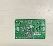
Hier ist eine neue PCB-Version von mir und Stallion.
Hengst, mein Freund, wollte eine Version mit Sicherungen und im Format 100*100mm.
Er möchte jedoch nicht, dass diese Version im freien Open Source landet.
Bei Interesse schreiben Sie mich direkt an.
Danke OSGO
View attachment 1125233
")
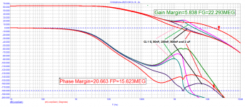
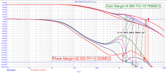
without inductance at the output, the performance for a real load is in great doubt - there are no phase margins.Hi @minek123
I am building my own board and want to use the Cascode implementation for the BJT Circlophone. I know you posted a schematic for the same in one of the previous posts.
1) How does it work, with reference to distortions compared to using 2 Zeners?
View attachment 1106451
2) Also is there a difference in working for the CCS shown in the schematic vs the one below this line.
View attachment 1106452
Could you or Elvee guide me to the correct one? The idea is to be independent of the supply changes if needed due to some unforeseen reason one being output power transistor availability.
Could Elvee or You explain how the Cascode transistor works? Does it work like a variable voltage-blocking Zener diode? I am pretty new in this discrete amplifier side.
Large signal propagation delay time - more than 400 ns. Preferably no more than 100 ns.
Attachments
Hi Petrov,without inductance at the output, the performance for a real load is in great doubt - there are no phase margins.
Large signal propagation delay time - more than 400 ns. Preferably no more than 100 ns.
Is you reply in anyway connected to my cascode query ?
Which software is used for this simulation as it does not look like LTSpice?
How is this Phase and Gain margin going to affect Circlophone performance in real world?
your reply will be benificial to all the boarders of Cicrolphone.
Hi @Elveewithout inductance at the output, the performance for a real load is in great doubt - there are no phase margins.
Large signal propagation delay time - more than 400 ns. Preferably no more than 100 ns.
with reference to Petrov's post 2326, I needed your expert guidance on the phase margin and gain margin with repect to Zoble Capacitor.
as i have already order pcb for fabrication and also the zoble - 5.6ohm and 22nF considering orignial schematic.
Since my board is SMD i would find it little trival to change the cap at a later date.
IIRC (it is more than a dozen years ago), I tortured my prototypes with all sorts of reactive loads, with a large square wave output signal, and they remained well-behaved without series inductance, but depending on the build, components, etc. your mileage may vary.without inductance at the output, the performance for a real load is in great doubt - there are no phase margins.
Large signal propagation delay time - more than 400 ns. Preferably no more than 100 ns.
Propagation and group delay aren't exactly the same thing, but anyway delay by itself is not problematic: it happens all the time in transmission lines, free air transmission, digital processing blocks, etc.
What is important is the constancy of the delay vs. frequency, or in other words a linear phase.
Your phase plot shows that the phase remains close to 0° for the whole audio bandwidth, which is what really counts.
If the GD of 400ns disturbs you, it can be tweaked by changing the values of the filter and coupling caps, but from an audibility POV, the effect is going to be minimal
@Elvee, it was not my 400ns but Petrov's post that i was trying to understand with your help.IIRC (it is more than a dozen years ago), I tortured my prototypes with all sorts of reactive loads, with a large square wave output signal, and they remained well-behaved without series inductance, but depending on the build, components, etc. your mileage may vary.
Propagation and group delay aren't exactly the same thing, but anyway delay by itself is not problematic: it happens all the time in transmission lines, free air transmission, digital processing blocks, etc.
What is important is the constancy of the delay vs. frequency, or in other words a linear phase.
Your phase plot shows that the phase remains close to 0° for the whole audio bandwidth, which is what really counts.
If the GD of 400ns disturbs you, it can be tweaked by changing the values of the filter and coupling caps, but from an audibility POV, the effect is going to be minimal
I have pretty much short path on my board but again i am not an expert at pcb design so lets see, ordered parts from element14 ( Farnell ) something are arriving soon, some after a week and half.. PCB should arrive mid next week.
With regard to sustainability requirements, practice suggests that the minimum reserves to ensure sustainability should be as follows:Hi Petrov,
How is this Phase and Gain margin going to affect Circlophone performance in real world?
in phase - at least 30 degrees;
in amplitude not less than - 3 dB.
Moreover, these reserves should be at any real load. In tests, a reactive load is most often used in the form of a capacitance in parallel with an active resistor.
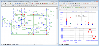
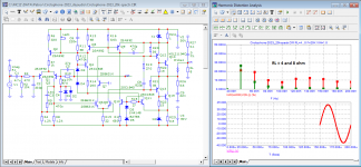
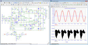
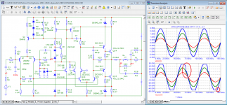
View distortion products at 10 kHz with a notch filter. You need to watch after 1.5 ms - after the end of the transients in the notch filter.
If you look at the output voltage, everything looks beautiful, but at the filter output we see distortion products from the soft excitation of the amplifier.
Try the same test with 50nF, 100nF, 500nF and 2uF reactive loads
When it comes to signal delay, many refer to it as tape recording. Today I recorded it, but you can listen to it in a year or two - the delay does not affect anything. For such colleagues, I would advise you to study the meaning of the Hafler SWDT test, and its application by Bob Carver to get the sound of a transistor amplifier indistinguishable from the sound of a reference tube amplifier. About vector errors can be found in the book by Jiri Dostal.
Attachments
The Absolute Sound_ May/June 2012
https://www.moremusic.nl/reviews/passlabs/XP-30-TAS.pdf
Cyrill Hammer:
«Perfect performance in the time domain is no less important. This is especially true of amplifiers based on negative feedback. The theoretical concept of negative feedback is very powerful, and the simplified mathematical equations describing this concept do hold true. But they are only valid if the design addresses the limitations of the concept. The time delay from input to output must be zero! Obviously in real life this is not possible. There are two ways to deal with this problem. Either you just do not apply any negative feedback at all to your design (while giving up the advantages of the concept) or you do speed it up to the level (200 MHz in the case of the Soulution 700 and 710) of a few nanoseconds of time delay from input to output, where timing errors are so small that they do not have any audible impact on the sound. Once you decide to go the latter way a whole bunch of new challenges suddenly arise. Thermal conditions, stability of supply voltages, high-frequency designs, noise induction etc., etc.»
Don't worry too much: the design has been tried and tested by many builders, in different versions and shapes, and they were 99% successful@Elvee, it was not my 400ns but Petrov's post that i was trying to understand with your help.
I have pretty much short path on my board but again i am not an expert at pcb design so lets see, ordered parts from element14 ( Farnell ) something are arriving soon, some after a week and half.. PCB should arrive mid next week.
Academically it could be correct. But do you have any suggestions to further improve Mr Elvee's schematic of Circlophone at present? I have built MOSFET version of Circlophone more than a year ago. It is continuously powered on and completely unattended. Parameters are all stable sustaining wide power mains voltage fluctuations etc and performance excellent which is prompting me to make another one.Cyrill Hammer:
«Perfect performance in the time domain is no less important. This is especially true of amplifiers based on negative feedback. The theoretical concept of negative feedback is very powerful, and the simplified mathematical equations describing this concept do hold true. But they are only valid if the design addresses the limitations of the concept. The time delay from input to output must be zero! Obviously in real life this is not possible. There are two ways to deal with this problem. Either you just do not apply any negative feedback at all to your design (while giving up the advantages of the concept) or you do speed it up to the level (200 MHz in the case of the Soulution 700 and 710) of a few nanoseconds of time delay from input to output, where timing errors are so small that they do not have any audible impact on the sound. Once you decide to go the latter way a whole bunch of new challenges suddenly arise. Thermal conditions, stability of supply voltages, high-frequency designs, noise induction etc., etc.»
Just got my SMD board (probably the first ) from the Fab, awaiting for parts - mostly should get them all by 25th of this month and will start the assembly but all depends on the time.
My layout may have faults just don’t go and start copying it. 🤣 I am dyslexic. You have been warned. Than don’t say my tranny’s got magic blue smoke.
My layout may have faults just don’t go and start copying it. 🤣 I am dyslexic. You have been warned. Than don’t say my tranny’s got magic blue smoke.
Attachments
Academically it could be correct. But do you have any suggestions to further improve Mr Elvee's schematic of Circlophone at present? I have built MOSFET version of Circlophone more than a year ago. It is continuously powered on and completely unattended. Parameters are all stable sustaining wide power mains voltage fluctuations etc and performance excellent which is prompting me to make another one.
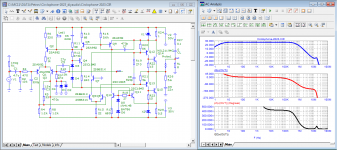
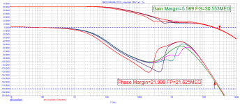
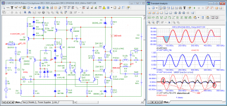
I double-checked the element values and ran amp model tests using Cordel's transistor models. There is no inductance at the output of the circuit, which is usually included to ensure stability when operating on a reactive load. A small inductance has a wire from the board to the output connectors. The linear inductance of a wire with a diameter of 1 mm is 1 μH. Therefore, even a wire 15 ... 20 cm long will have an inductance of 0.15 ... 0.2 μH. This inductance is often sufficient to ensure stable operation.
I simulated the operation of the model without inductance and with a small inductance.
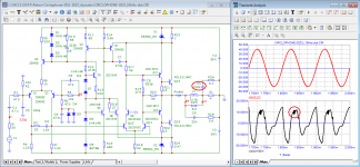
In fact, models even from Cordell do not fully take into account all the features of real transistors. Therefore, the amplifier model can only give a signal (bell), which should be paid attention to when establishing.
Pay attention to the Hafler SWDT test.
With a positive first half-wave of the burst, there is a shift of up to 30 mV; with a negative first half-wave, no shifts are observed.
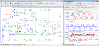
The model has small SID distortions (very short-term and amplitude not higher than non-linear distortions). I think that this is the merit of the high frequency of the first pole - above 10 kHz.
It should be noted that in a number of amplifiers, SID distortions exceed the products of nonlinear distortions by tens or even hundreds of times! I think that it is this type of distortion that has the greatest impact on sound quality.
Attachments
-
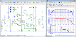 01_Circlophone-2023_Bode.png38.3 KB · Views: 75
 -
 02_Circlophone-2023_Loop-Gain.png21.8 KB · Views: 80
 -
 03_Circlophone-2023_L=0,15uH_Loop-Gain.png17 KB · Views: 63
 -
 04_Circlophone-2023_20kHz-clipping.png41.7 KB · Views: 67
 -
 05_Circlophone-2023_CL=100nF_10kHz-dist.png38.8 KB · Views: 72
 -
 06_Circlophone-2023_CL=500nF_10kHz-dist.png39.6 KB · Views: 68
 -
 07_Circlophone-2023_10kHz(+)_SWDT.png42.5 KB · Views: 75
 -
 08_Circlophone-2023_10kHz(-)_SWDT.png43 KB · Views: 80
Mr petr_2009,
Thanks for explaining the theory. But most of the Boarders do not have scope with them and I think quite a few do not use even LT spice simulation software to check the output of the amplifier waveform. I still do not understand what inference should I derive from your explanation. You may be correct theoreticaly but with this explaination many new builders will refrain from building Circlophone in future.
Things might prove wrong in simulation but I can still say that in real world Circlophone amplifier is a wonderful design by Mr Elvee.
In early days of this thread Elvee reported that simulations significantly diverge from reality in case of this amplifier (Circlophone).... I simulated the operation of the model ....
So, until you build and test real-life example of this amp (as many people did and found it functioning exactly as Elvee stated), your simulations are totally worthless - you just create useless noise here in (I suppose) malevolent effort to defame Elvee's good work (or at least, blow your own, disonant horn)...
Last edited:
I think I have to interject here !
The Circlophone is one of the few amplifiers that
my loudspeakers what others cannot.
Now it is always possible to apply simulations (via software). But they are only simulations, no more and no less.
I rely more on what I hear and what increases my well-being.
As a former technician at Siemens AG Munich and a practical physicist in the field of nano technology, such simulations are useless to me.
Now I have been retired for some time, but I still follow the Circlophone family sympathetically.
The speakers I have at home are the Teufel Ultima 40!
My measuring equipment consists of:
HAMEG - HM203-6
LEADER - 1021
NORDMENDE URV 356 tube voltmeter > 100kHz
DDS signal generator 20 MHz
Level meter MV - 73
Signal generator GF - 73
MOSFET Dual Power Supply 0-45 Volt (45-80V) 0-3.5 Ampere !
I operate the Teufel speakers with the following Circlophone:
+ /- 44Volt
max. current per channel approx. 2.8 Ampere
19" cabinet 3 HE
If you have any questions, please contact me !
OscarGolf
- Home
- Amplifiers
- Solid State
- ♫♪ My little cheap Circlophone© ♫♪