
No, just checking, there's many ways to skin a cat. 
(notice the location of the 3d mass in post 56)
Older automobile balancing machines used way higher rotational speeds due to much less sensitive sensors.
The sensor progress enabled unheard of balancing acts in the hot rod corner.
(notice the location of the 3d mass in post 56)
Older automobile balancing machines used way higher rotational speeds due to much less sensitive sensors.
The sensor progress enabled unheard of balancing acts in the hot rod corner.
Last edited:
Each subplatter was factory balanced (you can see the round traces where metal is missing if you examine closely the subplatters)
Two balanced subplatters are producing a balanced mass.
I took extra care with the silicone sheet that it doesn't alter this...
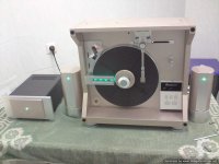
However, little pieces of metal had to be filed near the places where the extra weights are attached (for stability reasons) thus i knew i was a bit off.
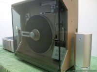
That's why i took the parts to the shop mentioned.
You should have seen the face of the man operating the machine when he asked at what rpm is this used and i replied at 45!
He is so used in balancing camshafts at thousands of rpm's that he said to me that at this slow speed it is probably not worth it!
So i said :"Let's balance it at 10 times that to make it worth your while" thus it was done at 500 rpm.
The lubricant for the spindle is based on 2 parts of special Peugeot gearbox lubricant for gearboxes with bronze gears plus one part of VdHul TLF II oil plus one part of "Super Dynamic" friction enhancer that i use in my cars for years with excellent results.
All are completely synthetic with no graphite or teflon additives.
Theis specks for max rotating speed,max working temperature and aging, make me sleep safe at night...
Two balanced subplatters are producing a balanced mass.
I took extra care with the silicone sheet that it doesn't alter this...
However, little pieces of metal had to be filed near the places where the extra weights are attached (for stability reasons) thus i knew i was a bit off.
That's why i took the parts to the shop mentioned.
You should have seen the face of the man operating the machine when he asked at what rpm is this used and i replied at 45!
He is so used in balancing camshafts at thousands of rpm's that he said to me that at this slow speed it is probably not worth it!
So i said :"Let's balance it at 10 times that to make it worth your while" thus it was done at 500 rpm.
The lubricant for the spindle is based on 2 parts of special Peugeot gearbox lubricant for gearboxes with bronze gears plus one part of VdHul TLF II oil plus one part of "Super Dynamic" friction enhancer that i use in my cars for years with excellent results.
All are completely synthetic with no graphite or teflon additives.
Theis specks for max rotating speed,max working temperature and aging, make me sleep safe at night...
EPISODE-9
Here are some more pictures that i could find in my other computer...
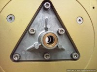
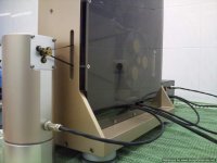
The first shows the spindle carrier with three bushings.
You can't see the fine work on their surface as it's covered in oil...
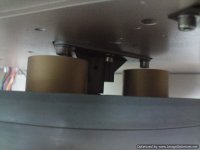
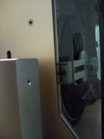
The second shows the clearance of the rotating weights with
regards to the aluminum surface.
It was calculated to be 12 mm on naked metal.I was taking account for 10 mm of bronze plate plus 1 mm of silicone sheet.
Unfortunately, when assembled (after painting) it proved that the paint layers
on four sides of metal were 1mm thick, and the weights would rub against the bronze plate! Bummer!
I couldn't shave metal of the rotating weights as this would ruin the balancing work done!
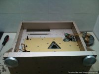
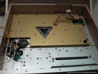
I had to take out the bronze plate, take it back to the CNC, and ask to shave away 1 mm of the surface in a circular pattern,exactly where the rotating weights would be.More painting job...
Pictures three and four is bronze plate before and after "shaving".
Now it was ok to assemble and the clearance was juuust enough for a sheet of paper to pass between.
Do you think that air turbulence of so close rotating surfaces will cause problems?Here is something to think in the future...
It was time to install the platter.
I leaned the chassis on a couple chairs (sitting on it's back) and a friend lying on the floor pushed the subplatter and spindle through the first rear bushing.
I was on top, filling the rear chamber with my lubricating formula and when it was full he pushed a bit more so i could fill the front chamber.
Slowly rotating back and forth the spindle would touch the front bushing
and push out all the excess oil for me to wipe.
A teflon washer (as in the rear) and safety clip was attached and the spindle was in place.
A quick check proved that there was absolutely no free play in the front to back motion.Strike another point!
Attaching the front platter was easy peasy, and it was secured temporarily with the original top part of the spindle as i had on order a different design, to accommodate my new heavy duty clamp.
I was a bit nervous when i first gave it a spin, as after the rear weights incident, i was afraid that the same would happen for the front ones too!
Luckily enough, it seems that 1 mm of clearance is plenty for two sides paint
and the platter would rotate without anything rubbing.
A quick push test proved it was tight :it would stop moving after 6-7 rotations.
I was told to expect that, as the bushing surfaces were now treated and the middle bushing was around a "virgin" place of the spindle.
It was obvious that it needed time and rotations to settle...
I left it overnight to spin with one motor and the next morning it would spin
10-12 rotations with the same force.That's a nice progress for one night!
The motor was warm (not hot) and with renewed confidence i let it spin away
and started working on the tonearm...
Here are some more pictures that i could find in my other computer...
The first shows the spindle carrier with three bushings.
You can't see the fine work on their surface as it's covered in oil...
The second shows the clearance of the rotating weights with
regards to the aluminum surface.
It was calculated to be 12 mm on naked metal.I was taking account for 10 mm of bronze plate plus 1 mm of silicone sheet.
Unfortunately, when assembled (after painting) it proved that the paint layers
on four sides of metal were 1mm thick, and the weights would rub against the bronze plate! Bummer!
I couldn't shave metal of the rotating weights as this would ruin the balancing work done!
I had to take out the bronze plate, take it back to the CNC, and ask to shave away 1 mm of the surface in a circular pattern,exactly where the rotating weights would be.More painting job...
Pictures three and four is bronze plate before and after "shaving".
Now it was ok to assemble and the clearance was juuust enough for a sheet of paper to pass between.
Do you think that air turbulence of so close rotating surfaces will cause problems?Here is something to think in the future...
It was time to install the platter.
I leaned the chassis on a couple chairs (sitting on it's back) and a friend lying on the floor pushed the subplatter and spindle through the first rear bushing.
I was on top, filling the rear chamber with my lubricating formula and when it was full he pushed a bit more so i could fill the front chamber.
Slowly rotating back and forth the spindle would touch the front bushing
and push out all the excess oil for me to wipe.
A teflon washer (as in the rear) and safety clip was attached and the spindle was in place.
A quick check proved that there was absolutely no free play in the front to back motion.Strike another point!
Attaching the front platter was easy peasy, and it was secured temporarily with the original top part of the spindle as i had on order a different design, to accommodate my new heavy duty clamp.
I was a bit nervous when i first gave it a spin, as after the rear weights incident, i was afraid that the same would happen for the front ones too!
Luckily enough, it seems that 1 mm of clearance is plenty for two sides paint
and the platter would rotate without anything rubbing.
A quick push test proved it was tight :it would stop moving after 6-7 rotations.
I was told to expect that, as the bushing surfaces were now treated and the middle bushing was around a "virgin" place of the spindle.
It was obvious that it needed time and rotations to settle...
I left it overnight to spin with one motor and the next morning it would spin
10-12 rotations with the same force.That's a nice progress for one night!
The motor was warm (not hot) and with renewed confidence i let it spin away
and started working on the tonearm...
Attachments
Last edited:
EPISODE-10
I had in my possession two different LT-5V tonearms and
a LT-1 tonearm which looked in many parts identical.
After a quick measuring, i found out that the tubes were identical in size.
So i decided to use the titanium tube of the LT-1V (filled with internal butyl dampening, plus some Acousta-Stuff fibers that i had laying around) and it's locking collar.
For headshell i was going to use a Sony Vega magnesium one bought from Japan.
I saw off its protruding finger lift (not needed in a auto lift tonearm).
I also drilled a series of holes into it to lighten it even further (and maybe cut off some standing waves).
The cable used was VDHul MCS-300 monocrystal silver which was a bi**h to pass through.
The arm already had two grounding wires (one for the lower part and one for the rolling base of the arm) that were kept in original form.
Together with the four wires from the cartridge, they really have given me some hard time to pass them through the main bearing.
Let's just say that a generous amount of K-Y jelly was used...to a good effect.
Because the new assembled tonearm was around 10 grams lighter than the original
i carefully drilled out some aluminum from the back side of the main weight to get things balanced again.
Then i moved my attention to the parallel tracking per se...
The original base of the arm was moving on an inox steel rail (identical to the LT-1)
with one teflon roller on one side and one teflon slide on the other.
The lower part of the base is moving on another teflon roller against a steel shaft (that always looked to me suspiciously thin~flexible).
I suspect that the teflon slide was there to keep in check the arms free movement but by taking some pointers from the LT-1 arm, i thought i could do better...
I took one roller out of the donor arm,reversed it and fixed it in the place of the teflon slide.So the base was now rolling on two teflon rollers (more freely) and with a bit wider track,thus more stable.
By reshaping the teflon slide, placing it between the rollers and with the use of a pushing screw a had an elegant regulated way to tame the arms movement.Japan designers,you can now eat your hats!
Then i concentrated on the thin steel shaft against which the third lower teflon roller was placed and i attached (screwed and glued) a solid bronze rod to it making it completely inert.
A silicone sheet was glued on it's track for the roller to move onto and smoothen out any incoming vibrations.
A little lubrication to the three bearings and the arm was ready...
Getting the arm to work with lower tracking error margin (from 0.5 deg to at least 0.2 as my subsequent tests proved) was done not by electronic manipulation but from mechanical solutions that pushed the electronics to their limits.
I attached the steel base that holds in place all tracking mechanisms but did three modifications:
a) a silicone flange was placed between it and the aluminum chassis, that was secured in it's place with a lot more screws than the original.
b)I remodeled the plastic parts that were holding the sensor leds and opponent light sensors by taking them apart an extra 3mm.
c)I narrowed the sheet steel slit through which the leds beamed light to the opponent sensors by 1 mm.
The last two mods had as a result the sensors triggering the correction servos at lesser deviations from the vertical point.
Of course there was a trial and error procedure to determine the optoelectronics limit to all this...too lengthy to describe...
The end result was a success beyond my expectations: the arm's tracking was surefooted and with reduced tracking error...Plus it was a looker (in my eyes at least)!
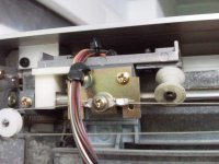
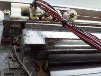
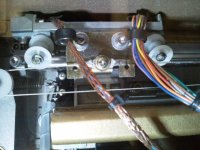
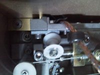
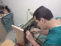
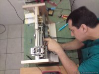
In the first picture is the original thing,in the second you can see the third wheel against the thin steel shaft,in the third and fourth is my second roller installed,in the fifth is the bronze rod attached to the shaft and in the last
you can see me sweating over the mechanism, trying for some fine tuning...
I had in my possession two different LT-5V tonearms and
a LT-1 tonearm which looked in many parts identical.
After a quick measuring, i found out that the tubes were identical in size.
So i decided to use the titanium tube of the LT-1V (filled with internal butyl dampening, plus some Acousta-Stuff fibers that i had laying around) and it's locking collar.
For headshell i was going to use a Sony Vega magnesium one bought from Japan.
I saw off its protruding finger lift (not needed in a auto lift tonearm).
I also drilled a series of holes into it to lighten it even further (and maybe cut off some standing waves).
The cable used was VDHul MCS-300 monocrystal silver which was a bi**h to pass through.
The arm already had two grounding wires (one for the lower part and one for the rolling base of the arm) that were kept in original form.
Together with the four wires from the cartridge, they really have given me some hard time to pass them through the main bearing.
Let's just say that a generous amount of K-Y jelly was used...to a good effect.
Because the new assembled tonearm was around 10 grams lighter than the original
i carefully drilled out some aluminum from the back side of the main weight to get things balanced again.
Then i moved my attention to the parallel tracking per se...
The original base of the arm was moving on an inox steel rail (identical to the LT-1)
with one teflon roller on one side and one teflon slide on the other.
The lower part of the base is moving on another teflon roller against a steel shaft (that always looked to me suspiciously thin~flexible).
I suspect that the teflon slide was there to keep in check the arms free movement but by taking some pointers from the LT-1 arm, i thought i could do better...
I took one roller out of the donor arm,reversed it and fixed it in the place of the teflon slide.So the base was now rolling on two teflon rollers (more freely) and with a bit wider track,thus more stable.
By reshaping the teflon slide, placing it between the rollers and with the use of a pushing screw a had an elegant regulated way to tame the arms movement.Japan designers,you can now eat your hats!
Then i concentrated on the thin steel shaft against which the third lower teflon roller was placed and i attached (screwed and glued) a solid bronze rod to it making it completely inert.
A silicone sheet was glued on it's track for the roller to move onto and smoothen out any incoming vibrations.
A little lubrication to the three bearings and the arm was ready...
Getting the arm to work with lower tracking error margin (from 0.5 deg to at least 0.2 as my subsequent tests proved) was done not by electronic manipulation but from mechanical solutions that pushed the electronics to their limits.
I attached the steel base that holds in place all tracking mechanisms but did three modifications:
a) a silicone flange was placed between it and the aluminum chassis, that was secured in it's place with a lot more screws than the original.
b)I remodeled the plastic parts that were holding the sensor leds and opponent light sensors by taking them apart an extra 3mm.
c)I narrowed the sheet steel slit through which the leds beamed light to the opponent sensors by 1 mm.
The last two mods had as a result the sensors triggering the correction servos at lesser deviations from the vertical point.
Of course there was a trial and error procedure to determine the optoelectronics limit to all this...too lengthy to describe...
The end result was a success beyond my expectations: the arm's tracking was surefooted and with reduced tracking error...Plus it was a looker (in my eyes at least)!
In the first picture is the original thing,in the second you can see the third wheel against the thin steel shaft,in the third and fourth is my second roller installed,in the fifth is the bronze rod attached to the shaft and in the last
you can see me sweating over the mechanism, trying for some fine tuning...
Attachments
ΕPISODE-11
The new top part of the spindle that secures the platter and provides a locking slit to the clamp had arrived.
Also a CNC job addressing some of the problems of the original one:
a)it secured the platter better by pressing a whole lot more surface.
b)it was slightly thicker (about half a mm more in diameter) to provide a tight fit for records with slightly bigger center holes.
c)was longer, to accommodate my new clamp.
Which was also ready:It was made from three aluminum parts and to take it's final shape some interesting parts were used :
a)Big rubber o-rings that were glued on the record label pressing area,
b)the releasing clips from a Canon FD lens cap and
c)a spring from a car valve.
These two together had a vice like pressing action on the records...
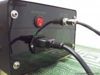
Also the PS box was ready with new thick black crackle paint
and with the faceplates (silver and champagne gold painted) ready to install.
I had ordered an over-specified toroidal transformer for powering the motors
that then i potted in epoxy resin (using a small inox pot),and for the rest i used
an off the shelf switching power supply.
I had installed a 5 Amps Corcom EFI/RMI filter in the AC line and beefed up the suppression caps using top quality PIOS.
A total parts upgrade was done on the board in the turntable with beefed up 105 deg, low ESR caps
(with bypass caps where applicable) ,more powerful power transistors with heatsinks and chips were renewed with equivalent more modern versions...
The power lines from PS/to turntable/to motors were shielded and lemo type locking connectors where used.
From a specialized internet store from US, i had received an assortment of
belts and chose the ones (left from right are different-left is shorter) that provided equal tension to the subplatter.
I was ready to test the motors action and synchronicity and did but the result was disappointing...
The two motors (wired in parallel) would start together but after a couple secs one would stop and the other kept going.Bummer!
It was not going to be that simple...
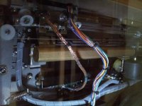
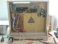
Pics are before/after, plus some from the wire spaghetti i was battling with...
The new top part of the spindle that secures the platter and provides a locking slit to the clamp had arrived.
Also a CNC job addressing some of the problems of the original one:
a)it secured the platter better by pressing a whole lot more surface.
b)it was slightly thicker (about half a mm more in diameter) to provide a tight fit for records with slightly bigger center holes.
c)was longer, to accommodate my new clamp.
Which was also ready:It was made from three aluminum parts and to take it's final shape some interesting parts were used :
a)Big rubber o-rings that were glued on the record label pressing area,
b)the releasing clips from a Canon FD lens cap and
c)a spring from a car valve.
These two together had a vice like pressing action on the records...
Also the PS box was ready with new thick black crackle paint
and with the faceplates (silver and champagne gold painted) ready to install.
I had ordered an over-specified toroidal transformer for powering the motors
that then i potted in epoxy resin (using a small inox pot),and for the rest i used
an off the shelf switching power supply.
I had installed a 5 Amps Corcom EFI/RMI filter in the AC line and beefed up the suppression caps using top quality PIOS.
A total parts upgrade was done on the board in the turntable with beefed up 105 deg, low ESR caps
(with bypass caps where applicable) ,more powerful power transistors with heatsinks and chips were renewed with equivalent more modern versions...
The power lines from PS/to turntable/to motors were shielded and lemo type locking connectors where used.
From a specialized internet store from US, i had received an assortment of
belts and chose the ones (left from right are different-left is shorter) that provided equal tension to the subplatter.
I was ready to test the motors action and synchronicity and did but the result was disappointing...
The two motors (wired in parallel) would start together but after a couple secs one would stop and the other kept going.Bummer!
It was not going to be that simple...
Pics are before/after, plus some from the wire spaghetti i was battling with...
Attachments
-
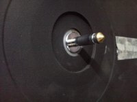 Photo0236-Optimized.jpg23.1 KB · Views: 139
 -
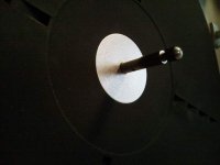 Photo0252-Optimized.jpg16.2 KB · Views: 89
 -
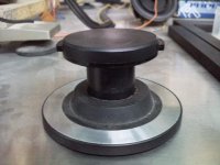 Photo0234-Optimized.jpg27.8 KB · Views: 86
 -
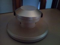 Photo0253-Optimized.jpg17.8 KB · Views: 88
 -
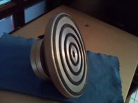 Photo0254-Optimized.jpg23 KB · Views: 91
 -
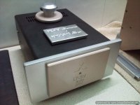 Photo0109.jpg41 KB · Views: 108
 -
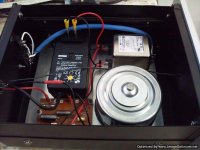 Photo0131.jpg49 KB · Views: 125
 -
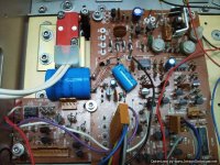 Photo0114_001.jpg78.7 KB · Views: 128
 -
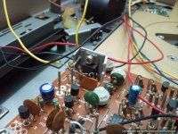 Photo0115.jpg67 KB · Views: 117
 -
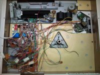 Photo0116.jpg75 KB · Views: 112
EPISODE-12
It was obvious that some kind of feedback was present in the regulating mechanism
that was cutting the power to levels enough for one motor only...
Was it sensing the different resistance of the combined motors?
I tried to compensate for it with no results:either one motor would work or none!
With the schematic in hand i tried to find my way through the possible interactions...
I am a vet, not an electronics engineer and my present level of knowledge was not helping
( i am working on it though!)
So i asked for the help of two friends who make their living with electronics/automation.
I have send them both the schematics and asked for a solution.
After a while they both came up with the same answer!
They advised on making a small buffering circuit so that we could trick the on board electronics
into not sensing the second motor.
Some veroboard examples of this buffer circuit were made with small variations on the resistors
and were subsequently tried.
Gradually we have accomplished that the second motor would start and keep spinning.
There was a certain resistor values "window", within which the whole thing would work.
Loose that and stabilization problems appeared.
But even when things looked right ,they actually weren't! All it took was a small adjustment on the
front strobo pots and the whole thing would go haywire!
This was not acceptable! No way i was going to put up with this!
Three months had passed with me battling the crazy tempered electronics and i was getting devastated.
Then, like my ancient compatriot Alexander the Great, i thought that instead of trying to untie the knot, i could just cut it!
I had two original boards, and i could use the second to power the second motor!No more interactions, no more problems...
It was a good thing that i had ordered three times the transformer power needed,
and indeed initial tests showed me that the second board would not bring them to their knees.
I was so lucky that i could just barely fit the second board on the other side of the subplatter!
So i did the same parts upgrade to the second board too, and drilled and tapped the places for the securing bolts.
I did all the connections with the proper places and assigned the second motor to the second board.
Time for the big test again ... and no it was nowhere near (AGAIN)!
What the h**l was wrong?THIS SHOULD WORK!
I let the whole thing aside for a week and tried to look things from other perspectives...
Then i came back with one thought: what things do the two boards share?
a)their mutual transformer
b)the function board (start, stop, forward, backward, repeat, 33, 45) and the tonearm "resting place" sensor that stops the platter from spinning.
c)the strobo trimmer pots.
I took out an original transformer and associated circuit and powered the second board with it.
No cure!
I took out and connected a second function board to control the second motor.
No cure.
I used a second sensor to signal the second board electronics about "tonearm resting".
No cure.
I used a second set of trimmers to fine-regulate the speed of the second motor
SNAP!ALL IS WELL!SOMEBODY PLEASE PINCH ME!
At last the motors would start and accept regulation from the onboard master trimmers
AND the front fine tuning trimmers as long as i used two for the 45 and two for the 33 speeds.Problem solved-almost!
How the h**l was i going to incorporate a second set of trimmers on the front?
SNAP!I wasn't!There are twin pots available!
Internet to the rescue and VOILA a specialized guitar shop in Germany sells exactly the same ALPHA 5KOhm pots in twin form!
A week later they were in my hands,and they would juuust barely fit in the limited space i had.
The motors where working great and the speed had a stability that i had never seen in the original turntable before!
Of course a 6+ kilo platter helps, but the two motors had an iron grip on things...
The rest should be like a walk in the park...
SOV,
I've been following this thread with great interest and would like to thank you for taking the time and effort to document and present the details of what seems to be a lengthy and sometimes frustrating project.
The very fact that you have stayed with it, even when faced with difficulties as you have described above, speaks volumes about your character and dedication. I only wish that I possessed those qualities to the extent that you have amply demonstrated!
Again, thank you.
Best Regards,
TerryO
It's good to know that at least some people are watching it!
Thanks for your kind words!
It's one thing, people who buy audio gear of the self saying "that is cool"
but totaly different to hear words of appraisal from the ones who are themselves diyers...
I am a meticulous and stubborn guy (not always to good effect).
I will keep hitting my head on the wall untill one of two breaks...
I am a meticulous and stubborn guy
No kidding !!!
That's the understatement of the millennium.
Why would someone be in the modding business if not meticulous?
It is an essential quality to be able to examine things and say that this or that
can be made better, because deep inside, you can't tolerate inferiority.
And if you can't tolerate it from others, you sure as hell can't tolerate it from yourself.
Practically speaking,it's the prefect recipe for an always unhappy,grungy,self destructive personality.
Only moments of happiness,are the ones you have when you finish a project, and that lasts for a little, until you focus on another "substandard" item.
Creative?Yes.Energy absorbing?You bet!Frustrating?By the bucketload...
It's the story of my life...
I've been following this thread from the beginning, too. I must say I'm mighty impressed by the high standards you are setting (and achieving!).
I have a question -- maybe I'm missing something obvious, but you have an odd number of weights (3) on the subplatters, wouldn't that produce cogging?
Keep the photos coming!!")
Kenneth
I have a question -- maybe I'm missing something obvious, but you have an odd number of weights (3) on the subplatters, wouldn't that produce cogging?
Keep the photos coming!!
Kenneth
Kenneth,thanks for your interest!
As i said i am not a mechanical engineer.
I am not aware of any physics law that says that
odd rotating weights produce cogging.If there is, please refer me to it so i can save myself of future mistakes(?).
Remember anyway that the two subplatters rotate in unison with an equally heavy
platter on the other side of the chassis -and that has 8 weights attached.
The reason for using three weights is obvious:three factory made holes that were an open invitation to install extra weight.
If they were four i would add four weights!
I suppose that if three extra weights add cogging (that i have not seen on strobo or
heard with my own ears) the lack of mass (holes) in the same places would add cogging too!
Mitsu engineers were working to a price target but to incorporate a flaw like that is a bit too much.
Anyone else knowing something about this?
Last edited:
Hi soundofvoid, thanks for answering! I'm not a mechanical engineer either, so I can't help with formulas
I just had this picture in my head, that the platter would continuously alternate between a position with lower potential energy (2 weights below the axle, 1 above) and one with higher potential energy (2 above, 1 below). Then maybe the torque required from the motor would have an AC component with a frequency of 3x the RPM.
But anyway the effect is probably too small to give any noticeable effect, given all the other masses involved! Perhaps someone with more knowledge of mechanics could speak up?
Have fun!!
K
EPISODE-12
With all the major problems solved,it was time for me to focus on the final presentation of my effort.
My baby should look as good as a million bucks!
And that was the time that the idea of a transparent back hit me!
But i didn't want to show off the two boards and the chaos of cables connecting them...
How about sheet steel covers that would cover them up, make things tidier and keep the electric pollution away from the signal wires?
Thus, i designed the sheet steel covers so that the boards would be out of sight, the cables would gather and pass all through the same route and the sensitive signal wires
would be outside of the covers in a clean open environment.
My order to steel press shop was to be made in 1.5 mm of sheet steel .
They took a while to make and in the meantime i was taking care of the wiring
plus i installed the output wires (VDHul D501 silver hybrid with the appropriate
RCA jacks) and a nice ground wire with superb termination - always hated cheap terminated ground wires!
When the covers arrived i had to drill in them the screw holes and drill and tap the
same to the turntable chassis-partly disassembling it.
The hard part was the shaping of the sheet steel of the second board.
It could not go under the subplatter and had to be cut in a round shape so that it
would "hug" the rotating subplatter but not touch it.
I took out the subplatter,screwed the cover in it's place, put back the subplatter and marked it's periphery on the cover.
Then i took it out and dremmeled my way through the cover leaving just one mm of free space between it and the subplatter.
Then the steel covers were prepped and painted to the dark grey colour that i had already used for other parts.
Carefully installed them to their places (with silicone flanges) and arranged the wires in an "pretty" manner using a transparent cable tidier.
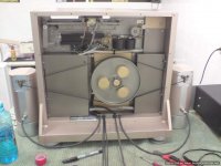
Now the back was looking great!It was a treat to watch the subplatter with the golden weights rotating!
Off to the plexi shop!
Plexi back (with beveled edges) and plexi front (in three pieces that i would mark and glue together in situ).
They were ordered in light grayish 1cm thick plexi.
I drilled all the holes in the plexi and made a nice opening for the cables (left motor-signal-power-right motor).The plexi was attached to the chassis with inox countersunk screws with a soft rubbery flange.At 1 cm thickness it was surely not a week point to the whole construction.
The front was attached to it's place with four plastic studs (drilled/glued into it) that were received by four cups on the four corners of the chassis.
These are used for speaker cloth frames but it was a great idea to incorporate them in my design to aid a secure cover placement of the heavy cover.
This was made to fit exactly the complex front opening because
a)I hate dust
b)I would like to play records with it in place and not worry about the sound
c)I have kids who bring friends (my kids are trained to keep a distance!)
On the sides of the front cover, two elongated holes were opened to provide a firm grip.It takes some force to pull it away!Officially child safe!
A third piece of 5 mm plexi was ordered for the back of the PS box.
I drilled all the openings and printed in my computer the letterings that would be behind it for an ultra clean look (Electrocompaniet style).
Also printed in clear self adhesive sheet the letterings around the strobo lights
for the turntable.All looked nice and tidy...
What is now left to do?
Actually nothing!
IT IS DONE!
With all the major problems solved,it was time for me to focus on the final presentation of my effort.
My baby should look as good as a million bucks!
And that was the time that the idea of a transparent back hit me!
But i didn't want to show off the two boards and the chaos of cables connecting them...
How about sheet steel covers that would cover them up, make things tidier and keep the electric pollution away from the signal wires?
Thus, i designed the sheet steel covers so that the boards would be out of sight, the cables would gather and pass all through the same route and the sensitive signal wires
would be outside of the covers in a clean open environment.
My order to steel press shop was to be made in 1.5 mm of sheet steel .
They took a while to make and in the meantime i was taking care of the wiring
plus i installed the output wires (VDHul D501 silver hybrid with the appropriate
RCA jacks) and a nice ground wire with superb termination - always hated cheap terminated ground wires!
When the covers arrived i had to drill in them the screw holes and drill and tap the
same to the turntable chassis-partly disassembling it.
The hard part was the shaping of the sheet steel of the second board.
It could not go under the subplatter and had to be cut in a round shape so that it
would "hug" the rotating subplatter but not touch it.
I took out the subplatter,screwed the cover in it's place, put back the subplatter and marked it's periphery on the cover.
Then i took it out and dremmeled my way through the cover leaving just one mm of free space between it and the subplatter.
Then the steel covers were prepped and painted to the dark grey colour that i had already used for other parts.
Carefully installed them to their places (with silicone flanges) and arranged the wires in an "pretty" manner using a transparent cable tidier.
Now the back was looking great!It was a treat to watch the subplatter with the golden weights rotating!
Off to the plexi shop!
Plexi back (with beveled edges) and plexi front (in three pieces that i would mark and glue together in situ).
They were ordered in light grayish 1cm thick plexi.
I drilled all the holes in the plexi and made a nice opening for the cables (left motor-signal-power-right motor).The plexi was attached to the chassis with inox countersunk screws with a soft rubbery flange.At 1 cm thickness it was surely not a week point to the whole construction.
The front was attached to it's place with four plastic studs (drilled/glued into it) that were received by four cups on the four corners of the chassis.
These are used for speaker cloth frames but it was a great idea to incorporate them in my design to aid a secure cover placement of the heavy cover.
This was made to fit exactly the complex front opening because
a)I hate dust
b)I would like to play records with it in place and not worry about the sound
c)I have kids who bring friends (my kids are trained to keep a distance!)
On the sides of the front cover, two elongated holes were opened to provide a firm grip.It takes some force to pull it away!Officially child safe!
A third piece of 5 mm plexi was ordered for the back of the PS box.
I drilled all the openings and printed in my computer the letterings that would be behind it for an ultra clean look (Electrocompaniet style).
Also printed in clear self adhesive sheet the letterings around the strobo lights
for the turntable.All looked nice and tidy...
What is now left to do?
Actually nothing!
IT IS DONE!
Attachments
-
 DSC00872.jpg65.1 KB · Views: 250
 -
 DSC01061.jpg64.9 KB · Views: 251
 -
 DSC01069.jpg65.7 KB · Views: 259
 -
 DSC01071.jpg63.2 KB · Views: 249
 -
 Samsung pictures 036.jpg59.9 KB · Views: 251
 -
 Samsung pictures 038.jpg58.2 KB · Views: 133
 -
 Samsung pictures 044.jpg24.4 KB · Views: 130
 -
 Samsung pictures 043.jpg56.3 KB · Views: 133
Last edited:
That is beyond belief.
It's good that you documented this so thoroughly.This thread will set some kind of future precedent,which will be referred to by many as a source of inspiration.I have no doubt that you have raised the bar for 'pull no punches' remodelling of a vintage classic.
Here's hoping that this is the first of many similar projects worldwide.
- Status
- This old topic is closed. If you want to reopen this topic, contact a moderator using the "Report Post" button.
- Home
- Source & Line
- Analogue Source
- My last turntable!