What exactly do you tweak in the basic decks beyond making them obviously reinforced in plinth material or giving them a suspension? Changing basic design, or making crucial parts heavy duty and/or better tolerance? New PSU is it redesigned or just heavy duty? What kind of carts you prefer, what is your phono preamp and how do they fair VS your digital rig? Preferring vinyl replayed on the hot rod TTs VS CD?
P.S. Are those CNC company guys taking projects like that in general? They showcase your work on their website claiming they undertook design and execution. They should have been claiming CNC execution only, not even assembly or finish work (as it will be naturally understood by the casual website visitor), never mind designing, shouldn't they? Ah, they made the TL-5V as in their title not the LT-5V, that will explain it. Maybe they will CNC IMF TLS-80 next.
P.S. Are those CNC company guys taking projects like that in general? They showcase your work on their website claiming they undertook design and execution. They should have been claiming CNC execution only, not even assembly or finish work (as it will be naturally understood by the casual website visitor), never mind designing, shouldn't they? Ah, they made the TL-5V as in their title not the LT-5V, that will explain it. Maybe they will CNC IMF TLS-80 next.
EPISODE-5
Next thing to do was to paint the metal parts...
I had tried in the past a couple body painters but i wasn't satisfied with the outcome.My baby deserved the best!
So i set up a little room (1.25 X 2m) in my practice's basement (that has good ventilation) and i was ready for work...
First a little sanding with a 400 paper to smoothen out rough corners and prepare the surface for the primer.
Then an epoxy primer in three coats.An UV lamp was used to speed the drying process.
I waited for a day before going on with wet/dry sanding with fine grade paper until the surface was satin smooth to the touch.After that, a thorough cleaning of all the surfaces was done for all the dust and particles to go away.This was done to all metal parts (bronze, aluminum , iron).Because all of these had front and back sides that had to be done in progression, and occasionally you have to respray until you get to that "perfect" stage ,i would say that this stage took me a month!
I had learn from previous efforts that paint does not cover anything!
If there is a slightest defect on the surface, the paint will only make it stand out more...
I was ready for color!The original LT-5V was silver,my next lightly modded one was painted black!Well,how about champagne gold with a little silver thrown in for good measure?
With a side panel from my Sony SCD-777ES in hand, i tried to find the closest champagne/gold hue.After three attempts with a different mix, i had a pretty good approximation.
I also bought an off the self silver paint (with a little "glitter" in it to spice things a bit) as i was going for a two-tone approach.
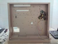
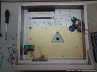
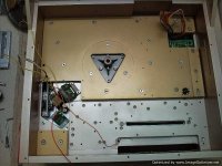
The other metal parts on the back side of the turntable, (mostly original parts) were
going to receive a darker gray color and all the bronze parts a golden one.
Of course, i had to completely dismantle the parallel tracking mechanism,the arm, and separate all the electronics,motors,sensors,cabling-the lot!
I had also to cover and protect from paint all the bushings and axles of revolving parts that were mostly made from self lubricating bronze and inox steel...
The paint was applied in four fine coats and each side was left to dry for two days under the UV lights.Then i would flip and paint the other side in the same manner.
For the two motor "towers" i had decided to paint the lower part and flat
surfaces silver and leave the rest champagne gold.
So at fist i painted them champagne gold,left them to dry,masked the "cheeks" and resprayed the rest in silver.Not an easy task...
When all parts were painted i left them dry out for a week before applying the final
medium gloss coat (four layers)They looked awesome!
And they were left to dry for another week before i tried a little hand rubbing with a
fine polishing paste and soft cloth...
Next thing to do was to paint the metal parts...
I had tried in the past a couple body painters but i wasn't satisfied with the outcome.My baby deserved the best!
So i set up a little room (1.25 X 2m) in my practice's basement (that has good ventilation) and i was ready for work...
First a little sanding with a 400 paper to smoothen out rough corners and prepare the surface for the primer.
Then an epoxy primer in three coats.An UV lamp was used to speed the drying process.
I waited for a day before going on with wet/dry sanding with fine grade paper until the surface was satin smooth to the touch.After that, a thorough cleaning of all the surfaces was done for all the dust and particles to go away.This was done to all metal parts (bronze, aluminum , iron).Because all of these had front and back sides that had to be done in progression, and occasionally you have to respray until you get to that "perfect" stage ,i would say that this stage took me a month!
I had learn from previous efforts that paint does not cover anything!
If there is a slightest defect on the surface, the paint will only make it stand out more...
I was ready for color!The original LT-5V was silver,my next lightly modded one was painted black!Well,how about champagne gold with a little silver thrown in for good measure?
With a side panel from my Sony SCD-777ES in hand, i tried to find the closest champagne/gold hue.After three attempts with a different mix, i had a pretty good approximation.
I also bought an off the self silver paint (with a little "glitter" in it to spice things a bit) as i was going for a two-tone approach.
The other metal parts on the back side of the turntable, (mostly original parts) were
going to receive a darker gray color and all the bronze parts a golden one.
Of course, i had to completely dismantle the parallel tracking mechanism,the arm, and separate all the electronics,motors,sensors,cabling-the lot!
I had also to cover and protect from paint all the bushings and axles of revolving parts that were mostly made from self lubricating bronze and inox steel...
The paint was applied in four fine coats and each side was left to dry for two days under the UV lights.Then i would flip and paint the other side in the same manner.
For the two motor "towers" i had decided to paint the lower part and flat
surfaces silver and leave the rest champagne gold.
So at fist i painted them champagne gold,left them to dry,masked the "cheeks" and resprayed the rest in silver.Not an easy task...
When all parts were painted i left them dry out for a week before applying the final
medium gloss coat (four layers)They looked awesome!
And they were left to dry for another week before i tried a little hand rubbing with a
fine polishing paste and soft cloth...
Attachments
-
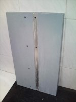 Photo0058.jpg27.8 KB · Views: 360
 -
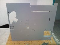 Photo0082.jpg40.7 KB · Views: 350
 -
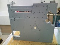 Photo0083.jpg51.3 KB · Views: 341
 -
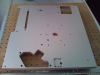 Photo0084.jpg50 KB · Views: 342
 -
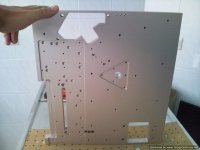 Photo0085.jpg45.7 KB · Views: 336
 -
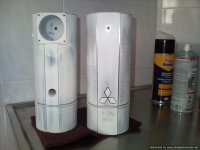 Photo0026.jpg60.9 KB · Views: 113
 -
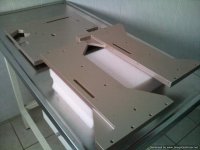 Photo0086.jpg56.6 KB · Views: 117
 -
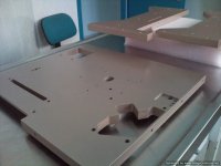 Photo0087.jpg51.9 KB · Views: 88
 -
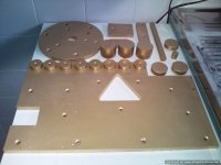 Photo0025.jpg56 KB · Views: 118
 -
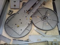 Photo0029.jpg93.7 KB · Views: 136
Salas,
first i choose designs that i like or others like!
Sometimes friends come and ask what they could do with a specific budget.
I visit all the audio shows and i am often puzzled by the amounts asked
for specific designs...There are immense gains for those with a little DIY skills.
BUT people don't always want to mess with diy situations...
Those, i turn to "all in one" designs like the DP-59L that i talked about earlier
(which by the way can be tuned nicely too!) that creams anything up to the 3000 euro mark.
Others are willing to take their chances and sail into the great unknown...
A turntable is a turntable:it spins a record!
To do this properly a) it has to have a stable speed (DD with double PLL wins hands down).
b)It must incorporate damping properties that actually work and keep out
of the signal, operational and external vibrations!
Usually i open and study the original design.If there is literature about it
i try to find what i can throught the net.
Then i decide what can be altered to gain better performance regarding the
a) and b).
Sometimes this is a better mechanical construction of a certain item,others a better power supply,others is to incorporate in the original design another way of dampening vibrations or redo whole parts...anything goes!
A friend with a DP-72L was floored from the difference made by simply exchanging the bottom board with a solid bronze one with better "feet"...
Tonearms/cartridges/wiring are more subjective parts and i tend to leave it
for the owner to decide...
My favorite pivoted arm designs are the Dynavector DV series and the Wilson Benesch Act-2.
Of course (I think it shows!) i consider parallel tracking the best way
(NOT in the Clearaudio way) but as all things mechanical has it's problems.
It is sad that with todays standard of electronics, noone has tried to make a modern servo controlled parallel tracking arm... They all go for the
messy air pump solution...
My preference is Van den Hul cartridges and cables.Cardas also...
I would love a Colibri but AJ advised against using it with my tonearm
(that has a medium/heavy active mass)
as it has a very short and delicate cantilever and it's suspension parameters
are less robust than the Condor.So i ordered from him a Condor metal
chassis that i "shaved" to my headshell's measure and then returned it
for adding the sensitive stuff...
I am a tubeholic and i love my Sonic Frontiers and Golden Tubes...
I use SS amps for driving the woofers only and leave the delicate job
for the tubes!
My phono is a SF Phono-1 SE+++ that gives me all i want.
My digital rig consists of a modified to the max Sony SCD-77ES for sacds and as transport for cds, a SF D2D-1 SE++ digital interface and a SF P-3
tube dac also modified to the max...
One vs the other?Hmmm,the analog wins but not with hands down.
Specific parameters of digital are better but the presentation as a whole
is always in favour of the analog...It's simply another perspective,
more humane,more organic, that suits our (mine at least) senses better.
Of course it depends on the quality of the software used!
Yes this is the CNC shop.They never thought that high end construction would be a bussiness worthwhile but i think they changed their minds...
I am dealing with them even defore they got the CNC machines...I gave them my pictures and said ok for using them in their site...
In the LT-5V construction they never knew what i was actually buiding (at least on the early stages).
It's ok,they have dogs!
Last edited:
It's ok,they have dogs!

Thanks for the lengthy account of your approach. I understand that you modify carefully design-wise the basic stuff, and you mainly reinforce structures when revising resonance and damping attributes along the way. Bearings and spindles would need revisions if platters are made heavier of course. And you keep the original PLL electronics. So you just move the trafo and smoothing to an external box and overspec those? There is a Revox parallel tracker, did you try on it, or is it only made in Japan for you? Revox docs
Attachments

You are basically right!
I have altered the bushings in my LT-5V since it has gone from 2.5kg to 6Kgs of rotating mass.
You have to predict this when you alter basic design parameters...
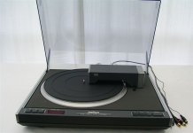
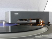
You must be referring to the Revox B795 model.
They can be easily found on ebay.
I have only seen one playing once some 20 years back.
Nobody has asked to do anything on it so i wouldn't know.
Usually REVOX users think that messing with their stuff is sacrilege!
It has a certain reputation for it's electronics and maintenance effort...
I have altered the bushings in my LT-5V since it has gone from 2.5kg to 6Kgs of rotating mass.
You have to predict this when you alter basic design parameters...
You must be referring to the Revox B795 model.
They can be easily found on ebay.
I have only seen one playing once some 20 years back.
Nobody has asked to do anything on it so i wouldn't know.
Usually REVOX users think that messing with their stuff is sacrilege!
It has a certain reputation for it's electronics and maintenance effort...
Last edited:
A factor worth mentioning is that analog has received a boost upwards in the last 10-15 years, all thanks to digital.
Finite elements analysis isn't only good for structural rigidity optimisation, but also for vibration calculations, higher order excitations, interaction simulation.
Faster&cheaper processors and larger ram/cache memory enable to run finite elements software on maison desktops, there's already ample freeware.
It may take to read a book on FEA and some practice, but there's not a requirement to know how to define the differential equations for the finite element matrices to run the show.
(i recall modelling a surface platform for navy divers before finishing the 1st FEM course, ashamed to admit it even took me several attempts to pass that bugger)
A lot of the current megabuck turntables are developed with FEA software, the David Payes TT likely the most finite element bragging.
Optimising a rebuild with FEA in the re-design phase puts you in the big boyz class. (maybe not everyone's cup of krasi though, so don't squeeze my bearing balls for mentioning)
I would stop to an SME 20/12 and be content if I wasn't broke for as far as I can remember me and I could purchase a good TT, but those Continuum must be OK to the millionaires. Who are the clients that the term High-End Audio was originally coined for so to attract status. Like spending on an SL1200MKII if having an $10M mansion. No bother. That caliburn is ugly looking though, isn't it?
Dr Audio Phil,
definitely one ugly looking Motha Frocker.
Each evening when i walk the cat, i need to pay attention every 30ft not to slip and break my neck on something that's a spitting image of the continuum tonearms.
Still, technology is blind.
I'm contemplating to build a kinematic mount platform for my TT, nearly identical to the one developed for fun friend Jochen Rake, without the heavy metal rack. Whether someone rather favors the butt ugly Transrotor Artus, instead of the insane beautiful Argos, is a personal thing.
Each evening when i walk the cat, i need to pay attention every 30ft not to slip and break my neck on something that's a spitting image of the continuum tonearms.
Peace with peculiarly shaped tone arms. Love spreads, cats puuurrr.

 )
)
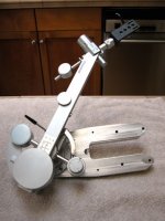
EPISODE-6
With all the metal parts painted and ready for assembly, i turned my attention
to other issues.
I dismantled all small boards/leds/electronics from the plastic fascia parts.
After a little sanding with a fine grade paper they were sprayed with a plastics primer
and were ready for painting.
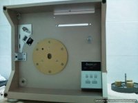
As i was going to use a stand alone clamp i designed a different arm for the track metering scale.
The original plastic arm had the metering scale on top while in my design it was in the middle of the arm and could be viewed through an opening.
I also thought of rear facing leds that would illuminate the record surface to make track selection easier.
The new arm was made by cutting parts from two arms ,adding a solid aluminum block in the middle (with the opening already milled in) filling the gaps with a hard epoxy resin
and then drill and tap in the resin the places for the screws that would hold the rear panel with the led array attached.
It's base was also filled with epoxy resin to incorporate longer bolts so it would be stable anough for the new heavier arm.
It took me a week to fabricate this arm, "dremel" all the details and a couple more days to find the way to pass the powering cables through the arm joint
and through the chassis.
The crystall /strobo/33,45 pots cluster was next.
The red strobo leds were replaced with high intesity greens and the plastic protruding
pot "handles" were cut in solid inox steel.
The lamps of the crystal were a bit yellowish and were replaced with new ones.
The buttons cluster was also dismantled and sheet silicone inserts were placed under the buttons to improve the feel of the "clicking" action.
The buttons themselves were filled with resin and taken out for their "faces" to be painted in the same
silver color as the rest of the stuff.
Also the top of the tonearm was dismantled for the parts to ber painted.
I took extra care to protect the sensitive bearings from paint dust penetrating.
All these parts were painted with three coats of silver paint and then another three coats of high gloss lacquer.
All were left to dy for a week before assembling them.
Extra dampening with the form of self adhesive dynamat pieces was added under all the plastic pieces.
And then i started to put the whole thing together...
With all the metal parts painted and ready for assembly, i turned my attention
to other issues.
I dismantled all small boards/leds/electronics from the plastic fascia parts.
After a little sanding with a fine grade paper they were sprayed with a plastics primer
and were ready for painting.
As i was going to use a stand alone clamp i designed a different arm for the track metering scale.
The original plastic arm had the metering scale on top while in my design it was in the middle of the arm and could be viewed through an opening.
I also thought of rear facing leds that would illuminate the record surface to make track selection easier.
The new arm was made by cutting parts from two arms ,adding a solid aluminum block in the middle (with the opening already milled in) filling the gaps with a hard epoxy resin
and then drill and tap in the resin the places for the screws that would hold the rear panel with the led array attached.
It's base was also filled with epoxy resin to incorporate longer bolts so it would be stable anough for the new heavier arm.
It took me a week to fabricate this arm, "dremel" all the details and a couple more days to find the way to pass the powering cables through the arm joint
and through the chassis.
The crystall /strobo/33,45 pots cluster was next.
The red strobo leds were replaced with high intesity greens and the plastic protruding
pot "handles" were cut in solid inox steel.
The lamps of the crystal were a bit yellowish and were replaced with new ones.
The buttons cluster was also dismantled and sheet silicone inserts were placed under the buttons to improve the feel of the "clicking" action.
The buttons themselves were filled with resin and taken out for their "faces" to be painted in the same
silver color as the rest of the stuff.
Also the top of the tonearm was dismantled for the parts to ber painted.
I took extra care to protect the sensitive bearings from paint dust penetrating.
All these parts were painted with three coats of silver paint and then another three coats of high gloss lacquer.
All were left to dy for a week before assembling them.
Extra dampening with the form of self adhesive dynamat pieces was added under all the plastic pieces.
And then i started to put the whole thing together...
Attachments
-
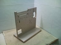 Photo0090.jpg50.3 KB · Views: 322
 -
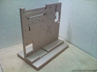 Photo0091.jpg53.3 KB · Views: 310
 -
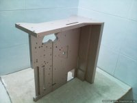 Photo0092.jpg51.9 KB · Views: 65
 -
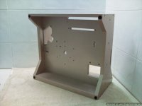 Photo0094.jpg49.8 KB · Views: 60
 -
 DSC00831.jpg50.7 KB · Views: 65
 -
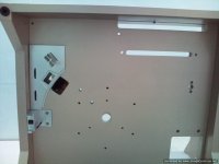 Photo0100.jpg45.1 KB · Views: 65
 -
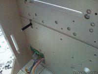 Photo0102.jpg56.7 KB · Views: 59
 -
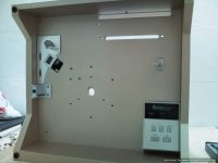 Photo0103.jpg51.4 KB · Views: 63
 -
 DSC00836.jpg35.5 KB · Views: 66
 -
 DSC00840.jpg41.3 KB · Views: 67
EPISODE-7
I already had in my disposal sheets of different materials whose characteristics i had tried
when the metals were naked (not painted).I was looking for pliable/absorbing materials
that would enhance the connection between different metals,absorb resonant energy,without being thick or messy to work with.
With my stethoscope in hand (in ear?) i tapped away to find what was best.
Sheets of rubber,hard silicone,soft silicone,dynamat and dynamat like materials were tried in succession.Dynamat was best in absorbing the energy from the metal attached to, but a)it didn't "connect" the two metals (you could hear a different pitch if you heard
aluminum or bronze) b)was thick (about 2.5mm throwing my space calculations way off)
c)was messy,as you have to "glue" it to at least one surface and d)from my experience it ages fast (especially in dry warm climates) and looses it's dampening characteristics when it's oily nature dries out.
My next best choice (and the one used) was soft silicone sheet that comes with peel off
protecting plastic sheets at both sides.This is so soft that when you press your finger
on it, you can see your fingerprint for a minute or so!
Those of you who refill their ink cartridges may have encountered this material as protection for the sensitive cartridge heads.
With this material between metals you could see them gel together so nicely that you had a hard time separating them.I remember when once i had to unscrew the rear bronze plate to feed under it the cables powering the illuminating leds,i couldn't separate
the two metals and had to leave them overnight standing with only one loose screw.
It was noon the other day that they came apart!
So the bronze parts were screwed on the aluminum on both sides nice and tight
with this silicone sheet (1,5 mm thick,reduced to 1mm after screwing pressure was applied).The result was an enormously rigid and damped chassis behaving like one solid piece and weighing alone more than 55 kilos.
Attachments
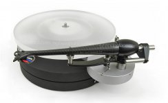
ΕPISODE-8
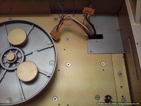
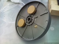
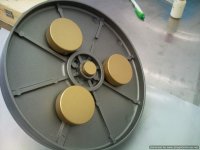
Some of you watching (?) this will ask :why not go for a bigger front bronze part that would cover as much area under the platter as possible (up to the rim?).
Well, i would have done it this way but i didn't because the space left (31 mm)
was used for attaching weights on the periphery on the underside of the platter.
The reason for this (as seen in many turntables,see Gyrodeck) is to increase rotational inertia which promotes the speed stability.
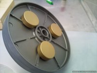
I have opted for round bronze disks with a diameter of 3 cms and a height of 1 cm.
That left me 1mm free space from the chassis attached bronze disk.
I marked the places on the underside of the platter, drilled and tapped the holes and screwed in place the weights (added a little glue just to be sure).
This produced a total weight of 2550 grams.A nice start.
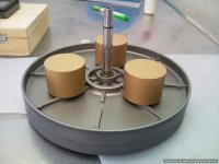
The original turntable did not match the weight on one side of the spindle to the weight
of the other...I don't know why, but this was all wrong in my book!
So i calculated the weight of my new clamp and choose to say that a typical record
would be around the 180 gr mark.
This produced a total frontal weight of 3100 gr.
To get the same weight on the subplatter side,i used two original subplatters each one facing the other (with a silicone sheet between them) attached with three (two-parted)
weights that would pass their screws through three factory cut openings.
It sounds more complicated than it really is...
With careful CNC trimming of the weights i achieved perfect balance...
So with a record in place i would have a total (give or take - depending on the actual record weight) of 6.2 kilos of rotating mass equally balanced.
The spindle carrier received three more holes for a total of six M5 securing bolts.
The two original bushings were tapped out, given an inspection and proved ok.
To aid lubrication a spiral route was cut on their axle facing surface with a "stop" at the end of the front and back one,without a stop on the new middle one.
The "stop" was there to keep the lubricant from spilling out whereas in the middle
bushing there was no such need.Four tiny holes where drilled though the body of the middle bushing to equalize the lubricant pressure on the two "chambers".
Originally there was no middle bushing but i took one out of a spare spindle carrier,modded it to my wishes,and then gently tapped it back to the center of the spindle assembly that i was going to use.
The reason for all this is that there was now
more support to the axle and zero "bending" in the middle due to the increased weight.
See the pictures...
Some of you watching (?) this will ask :why not go for a bigger front bronze part that would cover as much area under the platter as possible (up to the rim?).
Well, i would have done it this way but i didn't because the space left (31 mm)
was used for attaching weights on the periphery on the underside of the platter.
The reason for this (as seen in many turntables,see Gyrodeck) is to increase rotational inertia which promotes the speed stability.
I have opted for round bronze disks with a diameter of 3 cms and a height of 1 cm.
That left me 1mm free space from the chassis attached bronze disk.
I marked the places on the underside of the platter, drilled and tapped the holes and screwed in place the weights (added a little glue just to be sure).
This produced a total weight of 2550 grams.A nice start.
The original turntable did not match the weight on one side of the spindle to the weight
of the other...I don't know why, but this was all wrong in my book!
So i calculated the weight of my new clamp and choose to say that a typical record
would be around the 180 gr mark.
This produced a total frontal weight of 3100 gr.
To get the same weight on the subplatter side,i used two original subplatters each one facing the other (with a silicone sheet between them) attached with three (two-parted)
weights that would pass their screws through three factory cut openings.
It sounds more complicated than it really is...
With careful CNC trimming of the weights i achieved perfect balance...
So with a record in place i would have a total (give or take - depending on the actual record weight) of 6.2 kilos of rotating mass equally balanced.
The spindle carrier received three more holes for a total of six M5 securing bolts.
The two original bushings were tapped out, given an inspection and proved ok.
To aid lubrication a spiral route was cut on their axle facing surface with a "stop" at the end of the front and back one,without a stop on the new middle one.
The "stop" was there to keep the lubricant from spilling out whereas in the middle
bushing there was no such need.Four tiny holes where drilled though the body of the middle bushing to equalize the lubricant pressure on the two "chambers".
Originally there was no middle bushing but i took one out of a spare spindle carrier,modded it to my wishes,and then gently tapped it back to the center of the spindle assembly that i was going to use.
The reason for all this is that there was now
more support to the axle and zero "bending" in the middle due to the increased weight.
See the pictures...
Attachments
-
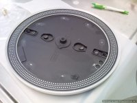 Photo0049.jpg74.8 KB · Views: 95
 -
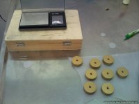 Photo0050.jpg53.5 KB · Views: 85
 -
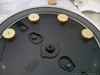 Photo0051.jpg63.5 KB · Views: 82
 -
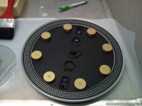 Photo0052.jpg83.2 KB · Views: 93
 -
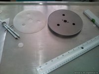 Photo0039.jpg54.1 KB · Views: 85
 -
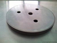 Photo0040.jpg48.8 KB · Views: 76
 -
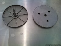 Photo0041.jpg47.5 KB · Views: 54
 -
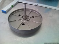 Photo0042.jpg58.8 KB · Views: 69
 -
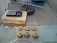 Photo0043.jpg53.5 KB · Views: 75
 -
 Photo0044.jpg52.7 KB · Views: 86
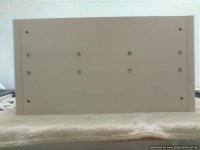
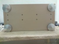
With careful CNC trimming of the weights i achieved perfect balance
How do you know ?
When both (platter and subplatter) were ready i took them to a specialized shop that balances camshafts for engines.
There, were given a spin and balanced within 1 gram at 500 rpm (speed that a turntable only dreams of).
Actually the platter even with my weights attached measured admirably well!
It's the subplatter that around 3 grams had to be shaved off.
You can see where the extra metal is gone on the last picture where a "nerve"
is cut off.
And some more photos...
Attachments

- Status
- This old topic is closed. If you want to reopen this topic, contact a moderator using the "Report Post" button.
- Home
- Source & Line
- Analogue Source
- My last turntable!