Here are the side pieces for my preamp.
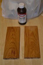
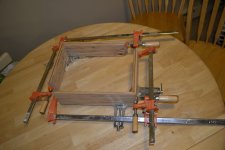
I picked up 24 sq. ft. of 3/4" x 6" unfinished hickory hardwood flooring on clearance for $10.
They are tongue n' groove which is nice since I will be flush mounting aluminum on the top of the chassis.
This stuff is beautiful.
I'm just going to finish it with gun stock oil and wax.
Final outside dimension of my preamp chassis will be 8.75" x 12".
Attachments
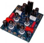
here are some pics from my aikido built
no noise, no hum
its a second one, frienkly, soundwise I preffer the octal one
Audio Pages: Aikido 5687 linestage
no noise, no hum
its a second one, frienkly, soundwise I preffer the octal one
Audio Pages: Aikido 5687 linestage
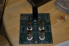
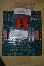
C4 Quandry
So......I have two baggies with C6 on them.
One is a pair of .68uF WIMA's and the other is a pair of 4.7uf Audiophilers.
I placed the WIMA's @ C6 where the silk screen has a nice rectangular space for them, is this correct?
Are the 4.7's really supposed to be for C4? It looks like there is ample room for them.
Attachments

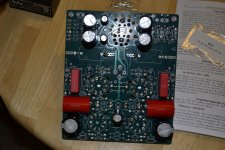
I know John messed up some of his kits, because he cut and pasted the PSU from one project onto the main circuit from another, so sometimes you get things like this.
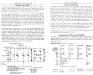
The wima caps will be something in the PSU. The 1uF/4.7uF would be the coupling cap (there is only one coupling cap in the signal path, or maybe two if that board has two outputs, as some aikido boards do). Can you post pics of the pcb from the top showing the whole lot, along with a photo of the schematic from the manual. Then we should be able to figure it out.
The wima caps will be something in the PSU. The 1uF/4.7uF would be the coupling cap (there is only one coupling cap in the signal path, or maybe two if that board has two outputs, as some aikido boards do). Can you post pics of the pcb from the top showing the whole lot, along with a photo of the schematic from the manual. Then we should be able to figure it out.

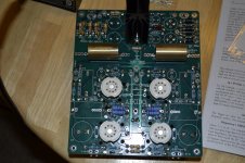
It appears that many of the variable value parts are tagged "This value takes experimenting.".
With this in mind I just guessed 470Ω for R17 since it was close to the middle of 100 & 1k.
I hope I don't blow anything up.
This may get powered up by Friday.
It all depends on how chassis building goes.
With this in mind I just guessed 470Ω for R17 since it was close to the middle of 100 & 1k.
I hope I don't blow anything up.
This may get powered up by Friday.
It all depends on how chassis building goes.
- Status
- This old topic is closed. If you want to reopen this topic, contact a moderator using the "Report Post" button.
- Home
- Amplifiers
- Tubes / Valves
- My First Tube Preamp