Hi If i am not mistaken E2=W*R=50*8=400V so for 50w we need 20 volts in to 8 Ohms The transformer has a ratio of 20,3 (sqrt(3300 ohm / 8 ohm)) approximately so we need a 400v swing in order to produce those 50w. Since this is a push pull transformer each winding swings the full B+ Am i wrong? Update: Yes i am, i forgot to change the rms to peak you are correct.
B+ is actually 580v but the tube manual asks for 600V up to 750V and the maximum possible output is more than 160W for two tubes per channel (4 pentodes in total) if i am reading the datasheet correctly. Tube manual here http://www.r-type.org/pdfs/829b.pdf In the datasheet after the tube pinout the first application is for AF amplifier-modulator. Well after testing i will know if the transformer is good or not.
Chris
Last edited:
Same calculations:
P = E²/R … inverting
E = √( PR )
E = √( 80 × 8 )
E = 25.3 VRMS
EP-P = 2 × 1.414 × 25.3 VRMS
EP-P = 71.54 VRMS … at speaker
EP-P VALVE = ½ ratio • EP-P SPEAKER
EP-P VALVE = ½ 20 × 71.54 VRMS
EP-P VALVE = 715.4 V
Again, which is even above the power supply recommended “in the manual”.
We haven't resolved if you are using 4 Ω speakers/load or not.
I've continued to use 8 Ω load, and output transformer tap.
GoatGuy
Yes i use 8 ohms, and in the tube manual the max b+ is 750 volts but the application data suggest 600v for the anode. Your calculations are correct , i forgot to change the rms voltage to peak to peak. For 50w i need a swing of 574v so the datasheet when it say 44w output power with 600v it means for the push pull setup and not per tube basis. Don't forget that i use 2 tubes per channel which means 4 pentodes per channel in total.
Anyway i only aim for 50W so i will see what this amplifier can output....
Chris
Anyway i only aim for 50W so i will see what this amplifier can output....
Chris
Last edited:
Yes 8 Ω, manual sez… max b+ 750 volts but app-notes say 600v. Anyway I only aim for 50 W so we'll see what this amplifier outputs …
E = √( PR );
… = √( 50 × 8 );
… = 20 VRMS
EANODE = ½⋅ratio⋅2⋅1.414⋅VRMS SPEAKER
… = ½ ⋅ 20 ⋅ 2 ⋅ 1.414 ⋅ 20
… = 565 VP-P per valve
So, supposing you keep a 600+ B+ going, you ought to be OK.
Looking forward to see your results.
GoatGuy
The impedance the tube "sees" depends on the condition it works in.Correct but it has two 3.3 Kohm windings not 3.2 The 829B has a plate to plate internal resistance of 13750 Ohm and because this transformer is a little difficult to construct i decided to parallel the two pentodes and use two tubes so each tube has a plate resistance of 13750 /2 = 6875 ohm but since the two pentodes are in parallel now each tube has an anode resistance of 3437 ohm hence the transformer windings. To be honest i have read this information here Google Groups
Chris
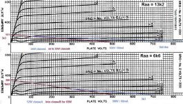
With 2x3.3k the Raa is 4x 3.3k.
Operating in class A both sides work together, each output side is charged with 6.6k but when it goes into class B each side is on it's one (other side is cut-off) and has to pull 3.3k
Mona
Operating in class A both sides work against each other, each output side is charged with 6.6 kΩ but when it goes into class B each side is on it's one (other side is cut-off) and has to pull 3.3 kΩ
Hmmm… seems to me that letting either valve go into cutoff is a recipe for a hard-to-compensate-for distortion knee event. I would think — especially for us audiofool types — that both valves should always be in Class-A conduction conditions, right?
Indeed, it seems to me that how I have long thought of as optimal for valve based push-pull is almost identical to how I think of "bridged output" stereo amplifiers, where one channel receives the inverted input signal, and where the "hot" output binding posts of each channel then carry the double-peak-to-peak voltage amplified signal. Thus doubling output RMS voltage, but also potentially doubling the drive amperage.
4× output power?
Nah… still limited by the design, the heat sinks, and the available margin of nominal operation.
Still, the thinking is similar.
From thinking about "class B" at all, all I see is a series of non-optimal compromises, if either phase's valve has some nominal level of conduction at signal=0. Supposing we're talking about the phase that causes the valve to go into cutoff, at that moment and for the increasingly "cut-off direction" signal, not only does the other valve do all the work, but its ability to provide enhanced voltage and current drive diminishes. The cutoff tube is non-participating.
But what do I know?
Nothing much, I guess.
GoatGuy
Understood. From what i understand the tube works in AB1 mode since 60ma for each 829b means that each valve will idle at 30ma with the grid never going positive. Max anode current for each 829b (both pentodes) is 220ma (110ma each halve). From initial tests the 829b produces too much heat for my liking with the filaments lit only so i decided to use a fan for cooling air flowThe impedance the tube "sees" depends on the condition it works in.
With 2x3.3k the Raa is 4x 3.3k.
Operating in class A both sides work together, each output side is charged with 6.6k but when it goes into class B each side is on it's one (other side is cut-off) and has to pull 3.3k
Mona
Chris
Well you are probably correct but i want to test it first and then see what i can do. What is the accepted maximum distortion for a music playing tube amplifier? From what i know 3% is the theoretical human ear limit but i consider 1% to be a good as 0,1% THD.Hmmm… seems to me that letting either valve go into cutoff is a recipe for a hard-to-compensate-for distortion knee event. I would think — especially for us audiofool types — that both valves should always be in Class-A conduction conditions, right?
Chris
Someone has used only one 829B tube per channel but the same transformer as the one i have with good results.
I searched for measurements but so far i can't find anything...
More info here
http://www.oocities.org/tinydaddy2000/FAQ.html
and here
http://www.oocities.org/tinydaddy2000/
Chris
I searched for measurements but so far i can't find anything...
More info here
http://www.oocities.org/tinydaddy2000/FAQ.html
and here
http://www.oocities.org/tinydaddy2000/
Chris
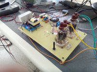
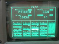
IT IS ALIVE! Without any feedback THD at 1Khz and 10w output in to 4 Ohms is 1,4% and at 30w 4%
There is a very low hissing sound but i have to be close to the speaker at about 50cm or 20-25 inches away from it, i don't know if this is normal or not.
I had some problems with oscillations which i solved by adding 1uf capacitors to the grid bias potentiometers but i will add one
at least tot he screens also. Now i am adding 1nf 1Kilovolt capacitors to the anode caps and screen. Later i will connect a bluetooth headset he he he
UPDATE:
All hissing is gone, it needed bigger capacitors on the bias smps converter (12v to -24vdc) output.
Chris
Last edited:
I AM SOLD! Now i am hearing music from a mp3 and i am ecstatic from the quality of sound... THD is much lower now because the hissing and a UFO like noise from one SMPS was included in the initial measurements but now the amplifier is absolutely quiet and i manage to bias the tubes spot on. In the initial measurements the output tubes were operating with only 5ma idle plate current each (10 each bottle, 20ma in total) just to be safe.Monday i will add a preamplifier stage and 10 or 20db of NFB, i don't think i need more than that. I will also update the schematic to reflect all changes i made. I want to thank you all for your KIND help and i think this site deserves a small donation (as much i can afford)
Chris
Chris
Last edited:
First congrads you have it playingThe 829B has a plate to plate internal resistance of 13750 Ohm and because this transformer is a little difficult to construct i decided to parallel the two pentodes and use two tubes so each tube has a plate resistance of 13750 /2 = 6875 ohm but since the two pentodes are in parallel now each tube has an anode resistance of 3437 ohm hence the transformer windings. To be honest i have read this information here Google Groups
Chris

The plate resistance has nothing to do with the impedance of the output transformer.It's more the supply voltage and the current capabilities of the tube for determing what load works best.
Here the load lines for two cases of Raa value.Asumed a supply 500V and bias 60mA.
Mona
Attachments
You are correct, i understood this yesterday only when i was reading a post about measured plate resistances of various output tubes. Meanwhile the only remaining problem is building a proper ultra fast rectification bridge for the 500 volts smps because normal rectifying bridges leak badly at 20Khz. Later i will try to raise the frequency to 50Khz because i think i can feel the high pitch noise in my brain... I will also try a one tube per channel scheme because i think 30 watts per channel are enough for me. BTW those ebay cheap dc converters work very well! It looks like the power supply will not cost much or be heavy as an anchor but i haven't decided yet because i like the reliability of iron...
Chris
Chris
Attachments
Last edited:
I read you loud and clear, this is what i got also but i was too lazy to fit them today because i was hearing songs from the 60'sI use UF5408 or HER208 for my builds. They work in my set up at 75kHz, whereas normal 1N5408 burn out in minutes.
Even playing through bluetooth with this lousy mp3 format the sound was better than my SS amplifier.Chris
Last edited:
need help with gain oscillation
HI. Today i devoted the whole day chasing a strange gain oscillation on my ECC84 - DUAL 829B push pull amplifier The tubes are not oscillating exactly but when i apply 1Khz low level signal which produces a small output of about 1w there is an audible amplitude oscillation with a period of about 1 second which usually goes away after some minutes of operation. On the oscilloscope the amplitude is oscillating between 70-80% and 100% but there is no distortion whatsoever. It sounds exactly like someone is turning the volume up and then down with a period of 1 or so seconds. Now if i increase the input signal level the oscillation goes away and it doesn't come back until i lower the level again very much. I checked the preamplifier and phase splitter's output and there is no oscillation there, it only happens at the output tubes. I have checked both output tubes and also checked all usual things like grid stoppers etc. Also there is no negative feedback in the system, the system is open loop. Has anyone encountered this behavior again? Thanks in advance for your time.
Chris
Last edited:
Ok i solved the issue. It was coming from positive feedback through the air from the output tube plate cables to the UNSHIELDED input cable of about 1 meter. Fitting a shielded input cable resolve this but i will also fit shielded plate cables, probably RG58 or something that can stand the voltage. Now i did measured the THD and it is 1,9% for 30w and 1,5% for 10w in to 4 ohms running open loop.
Chris
Chris
Attachments
one final question.
After trying various schemes and tricks THD came down to 1-1,2% at 70w and 0,7% at 40w in to 4 Ohms load (actual speakers) I really like the crystal clear sound of the amplifier and so everyone else that hears it so i need to ask if NFB is actually needed for other than THD reasons. I am thinking to leave the amplifier like this without negative feedback.
Chris
Try it and see. A smidge of negative feedback can make the bass sound tighter/better, and can give the amplifier a "cleaner" sound in most situations, at least in my experience. The real benefit is reducing IMD type distortion, which many say can make the amplifier less fatiguing to listen to.
Hi. I tried about 3 to 6 db and i still can't decide although the change is very profound.
Anyway the 2 hz oscillation gremlin is back so i need to chase it further. It looks like a 1- 2 Hz oscillation on top of the 1Khz test signal and it vanishes when i turn the volume up enough and it doesn't come back until i restart the amplifier. Tomorrow i will change the coupling capacitors and check again because i have done everything imaginable and i still can't remove this oscillation. If i remove the output stage coupling capacitors the oscillation stops but i soon as i connect them again the oscillation starts again even without any input signal and because it is a very low frequency oscillation it is visible on the anode current measurements.
Chris
although the change is very profound.Anyway the 2 hz oscillation gremlin is back so i need to chase it further. It looks like a 1- 2 Hz oscillation on top of the 1Khz test signal and it vanishes when i turn the volume up enough and it doesn't come back until i restart the amplifier. Tomorrow i will change the coupling capacitors and check again because i have done everything imaginable and i still can't remove this oscillation. If i remove the output stage coupling capacitors the oscillation stops but i soon as i connect them again the oscillation starts again even without any input signal and because it is a very low frequency oscillation it is visible on the anode current measurements.
Chris
- Status
- This old topic is closed. If you want to reopen this topic, contact a moderator using the "Report Post" button.
- Home
- Amplifiers
- Tubes / Valves
- my first post and a question