… I would imagine practically it takes the likes of a Wheatstone Bridge to perform a zero-current measure of a self-biased floating grid. Even gigaohms would load the thing!
Today it is trivial. A TL072 buffer will not load most grid current.
See Radiotron Designer's Hnadbook 4th, pages 20-21 and 101-103. Typical high Ig is around 1uA. (5,000X the room-temp Ib of a TL072.)
A 1uA current is just-detectable on a passive 50uA meter. You won't get an exact reading but you can tell it isn't zero.
See also Guitar Amplifier Overdrive, Neumann and Irving, 2015. They ran tests on modern production 12AX7 types. They show the rise which has been mentioned, and also wide differences between "same type" tubes. Sloppy scan attached.
Attachments
As always a wealth of information to digest.
About the grid current although i didn't knew this I always believed that there is no pure on off thing, everything gets analog somewhere in its operating range.
For a strange reason i always prefered voltages around -3 or -4 volts for bias without ever thinking about grid current just because i never felt comfortable with tube that need -1 -1,5 volts for bias, too close to 0 volts.
Ah, you're right. I overlooked the kinetic energy of the drift electrons. Makes sense. In fact one's grid doesn't even need to be close to zero, right? If the distance from K → G is '1' unit, and G → A is 9 units (total 10), and if the curl of the electric field determines relative acceleration of the electrons, then by ∇×B or something close, you get a 1/d² relationship.
VA-VK (1²/(1+9)²) = ¹/₁₀₀ VA-K or so.
So when VA relative to VK is (e.g.) 200 V, then the electrons near the grid are only winging along at 2 V or so. Therefore, VG < –2 V is the cutoff.
OK, I'm happy now.
GoatGuy
Your fundamentals to derive the expression are an outrage to the physics involved. No offence intended.
I am waiting from yesterday for a proper answer, but you still ignore my request.
http://www.diyaudio.com/forums/tubes-valves/321952-post-question-8.html#post5423817
I know that you are a very busy guy, so please take a little time for my question.
More observations on grid-current as Vg goes through zero:
Triodes at Low Voltages.... By Merlin Blencowe bottom of page 2.
Triodes at Low Voltages.... By Merlin Blencowe bottom of page 2.
More photos
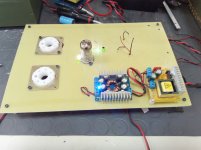
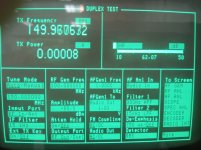
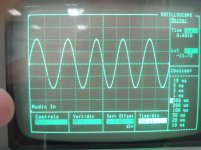
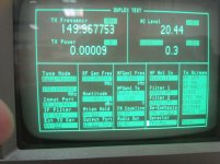
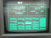
Here are some more photos. Please remember that this is a prototype for one channel just to check it's performance, the final construction will be very different. The SNR is about 62db (i don't know if this is good enough but remember that i don't use shielded cables for now so some 50Hz noise is getting in to the amplifier from the air and the instrument's own SNR is measured at 80db), the distortion 0,3% at the full output of 40Vpp (the instrument shows 20Vp+ not Vpp) for the 829b (the 829b's grid resistors are connected) and the preamplifier uses 200v. The 829b's filaments are tested and the converter with the blue led supplies 12,6v for them. What is not shown is the main high voltage supply which is out for modification and cooling enhancement.
Chris
Attachments
Last edited:
Today i finished the output tubes connections and voltages so while i am waiting for the output transformer i had the bright idea to lower the filament voltage of the ECC84 from 6,3Vdc to 5Vdc because i have so many 5V@6A switching modules that i hate to let them go to waste.
The results were fascinating to say the least, THD came down 0,1% S/N got up 2 db and output remained the same although i have the impression that gain came up a notch.
Now i am tempted to try even lower filament voltages...
Chris
The results were fascinating to say the least, THD came down 0,1% S/N got up 2 db and output remained the same although i have the impression that gain came up a notch.
Now i am tempted to try even lower filament voltages...
Chris
A small reduction in heater voltage will reduce noise; a bigger reduction will increase noise. This is because a small reduction cools the cathode space charge. A big reduction begins to eliminate the space charge, and then you get full shot noise without any space charge smoothing. By this point the cathode is exposed to ion bombardment so will not last as long.
THANK YOU VERY MUCH for the information!
If i understood you correctly i can damage a tube with low enough filament voltage, am i correct? Also do you think that 5v instead of 6,3 is a big change or i am safe? Of course the decision is mine so i am responsible if anything goes wrong, i am just asking for your opinion.
Chris
If i understood you correctly i can damage a tube with low enough filament voltage, am i correct? Also do you think that 5v instead of 6,3 is a big change or i am safe? Of course the decision is mine so i am responsible if anything goes wrong, i am just asking for your opinion.
Chris
In the few situations that I've gone to DC heaters I found low volting them to 5.5~5.6V worked well, good solution for DAC I/V stages or phono preamplifiers. A good friend of mine routinely does this for most of his signal tubes, even on AC heaters- he will place the tube(s) as the last in chain with low value series resistors in series with the filaments right at the socket.
The force over an electron with charge q and velocity v in the presence of an electric field E and a magnetic field B (aka Lorentz force) is given byAh, you're right. I overlooked the kinetic energy of the drift electrons. Makes sense. In fact one's grid doesn't even need to be close to zero, right? If the distance from K → G is '1' unit, and G → A is 9 units (total 10), and if the curl of the electric field determines relative acceleration of the electrons, then by ∇×B or something close, you get a 1/d² relationship.
F = q (E + v x B)
The acceleration of the electron is just
a = F/m = (q/m) (E + v x B)
It has nothing to do with curl/rot/∇x of anything.

VA-VK (1²/(1+9)²) = ¹/₁₀₀ VA-K or so.
So when VA relative to VK is (e.g.) 200 V, then the electrons near the grid are only winging along at 2 V or so. Therefore, VG < –2 V is the cutoff.
OK, I'm happy now.
GoatGuy
Could you please post a detailed derivation?
Today i changed the Ring of two CCS with a dual PNP cascode with LED bias and the measured change was dramatic. THD fell from 0,3 to 0,1 for full output with the output tube's grid resistor at 39Kohm because i have two pentodes in parallel (829b has 2 pentodes in each tube)
It looks that i hit the limit... I also want to say that the preamplifier stage before the cathodyne seem to like very low currents of about 1,8ma (the lower the current and the gain the lower the THD and a bias of -4,5V I don't know if this happens only with the ECC84 but i have tried nearly all combinations of bias voltages and anode currents.
Chris
Attachments
Last edited:
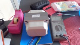
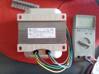
Today i got my one and only output transformer. I ordered it for 50w but it looks like it is made for 100w! I think it will handle at least 50watts of power... Monday is a big day, i will test for the first time the whole amplifier. I also plan to measure the anode idle current by measuring the ohmic voltage drop across the primary windings and the middle V+ wire (red in the photo), resistance is about 41,1 Ohm in one side and 46,1 at the other. I guess that the not uniform winding diameter results in different winding resistances but the turns are the same. Last but not least i plan to add one 10 ohm or so resistor in each 829b cathode for enhancing stability, is this a good idea or not?
In the photos visible are my all new FAKE DN2540N5 which of course do not work as they show infinite resistance between source and drain. I must admit that they look like one million dollars each...
Chris
In the photos visible are my all new FAKE DN2540N5 which of course do not work as they show infinite resistance between source and drain. I must admit that they look like one million dollars each...
Chris
Attachments
Last edited:
Its not that confusing: it is a push-pull transformer. There are 3 wires on the primary side. That would be "anode - B+ - anode". The 3.2 kΩ impedance is oddly stated, "x2" but in essence it is most likely a 3.2 kΩ to 4 Ω / 8 Ω transformer, as regular as you please.
GoatGuy
GoatGuy
It is a 3300 ohm push pull to 4 and 8 ohm transformer which has 2 windings of 3.3 KiloOhm.The 2x3.3kOhm on the transformer is very confusing. If each winding anode->supply is 3.3kOhm you get Raa = 13.2kOhm, but if Raa = 6.6kOhm the windings are 2x1.65kOhm ! So, what is it ???
Mona
Chris
Correct but it has two 3.3 Kohm windings not 3.2 The 829B has a plate to plate internal resistance of 13750 Ohm and because this transformer is a little difficult to construct i decided to parallel the two pentodes and use two tubes so each tube has a plate resistance of 13750 /2 = 6875 ohm but since the two pentodes are in parallel now each tube has an anode resistance of 3437 ohm hence the transformer windings. To be honest i have read this information here Google GroupsIts not that confusing: it is a push-pull transformer. There are 3 wires on the primary side. That would be "anode - B+ - anode". The 3.2 kΩ impedance is oddly stated, "x2" but in essence it is most likely a 3.2 kΩ to 4 Ω / 8 Ω transformer, as regular as you please. GoatGuy
Philip Lawrence <hitr...@iinet.net.au> wrote in message news:<3BEFB04D...@iinet.net.au>...- show quoted text -
Hi All The 829B works very fine in the Williamson configuration. Use 2 Tubes. Output transformer is a Millerioux XH36B 6K6 PP and the anode voltage 500V Grid 2 is held at 200V DC. Grid 1 at -20V and cathode current 60ma for each tube (2Tetrodes).Classic 5692 preamp. Output power 50 Watts. At 20W THD 0.09% IMD 0.07% and frequency response 20hz to 20 Khz at +/-0.3db ! Sounds very good. If someone has ...anode caps for this tube . Regards Pierre
Chris
OK, I might be as thick as a log, but here's what I calculate
I'm thinking “well, that seems like too much voltage swing for the usual B+ supply”, you know? What's the B+ here, 400 volts or so, or 380 V at the anode itself? Being PUSH-PULL, the voltage swing is only half per tube, so
Much better. But still that seems like a lot to ask of a tube: at B+ itself, that's maybe what 380 V? But at 380 V - 315 V we're at an anode of +65 V. Seems awfully low to me.
And that's my contention.
It doesn't seem likely that “distortion” is only 0.09% at 20 W output.
But I'm probably missing something.
Like a 4 Ω load instead of 8 Ω.
GoatGuy
3300 Ω ÷ 8 Ω = 412
√( 412 ) ≈ 20:1
P = IE …
P = E²/R
E = √( PR )
E = √( 20 W × 8 Ω )
E = 12.7 VRMS
EANODE = ratio • ESPEAKER
EANODE = 20 × 12.7 V
EANODE = 254 VRMS
EP-P = 2√(2) • ERMS
EP-P = 2.828 × 254 V
EP-P = 715 volts
√( 412 ) ≈ 20:1
P = IE …
P = E²/R
E = √( PR )
E = √( 20 W × 8 Ω )
E = 12.7 VRMS
EANODE = ratio • ESPEAKER
EANODE = 20 × 12.7 V
EANODE = 254 VRMS
EP-P = 2√(2) • ERMS
EP-P = 2.828 × 254 V
EP-P = 715 volts
I'm thinking “well, that seems like too much voltage swing for the usual B+ supply”, you know? What's the B+ here, 400 volts or so, or 380 V at the anode itself? Being PUSH-PULL, the voltage swing is only half per tube, so
VP-P EACH = ½ VP-P total
VP-P EACH = ½ 715
VP-P EACH = 308 V
VP-P EACH = ½ 715
VP-P EACH = 308 V
Much better. But still that seems like a lot to ask of a tube: at B+ itself, that's maybe what 380 V? But at 380 V - 315 V we're at an anode of +65 V. Seems awfully low to me.
And that's my contention.
It doesn't seem likely that “distortion” is only 0.09% at 20 W output.
But I'm probably missing something.
Like a 4 Ω load instead of 8 Ω.
GoatGuy
- Status
- This old topic is closed. If you want to reopen this topic, contact a moderator using the "Report Post" button.
- Home
- Amplifiers
- Tubes / Valves
- my first post and a question