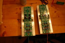
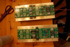
Much needed few days of vacation. For those who have not seen them, here are some pics of stage one of the build. As you can see, I have chosen two different methods of heat-sinking the diodes. At this point, I see no reason for heavy heat-sinking for the diodes. With just a single pair of fets, with 400mV across Rs, I have Ipk at 1.6A. Playing as loud as I can stand on my bookshelf FR units, the diodes that are freestanding barely get above room temperature. The diodes mounted to the heat-sink measure about 10 degrees warmer and i don't notice any real difference in sound from one channel to the next. I am going to try to get some working measurements this weekend, but we will see. At the very least, I will put an O-scope on the amp and watch what happens on both output and across diodes. I may get some distortion test, but I am working with a recently purchased emu 0404, that seems to be temperamental with Windows 7. May have to get a different card. I also hope to get the second pair of fets mounted and once again listen and measure. Tonight it was a Mini AJ vs. F5T V3 battle. I must admit, its fun having a Firstwatt Toe to Toe. More on that later.
Oh, one more thing. ZM, has treat for Greedy BOYZ like me.....again. (p.s. - PDF)
Oh, one more thing. ZM, has treat for Greedy BOYZ like me.....again. (p.s. - PDF)
Attachments
camping with the fam huh...and you didnt bring the project with you? This is DIYA blasphemy!!!!!
heh...good one
Rickrolled
heh...good one
How well do those wide heatsinks get the Tc of the centre located devices down to manageable levels?
I am sorry, but i don't understand the question. The main 4" x 10" heatsinks run at about 42C measured directly above the fet. In another project I have had a BA output stage mounted on them using same rail voltage, with Ipk per sink at 3A. At this level, you are getting into the 50-55C range. Back Ipk down to 2.5 and you are safely within 50C.
Andrew, what tells you that? What areas are you thinking are not part of the Avg enough? I have looked at many boards with spread apart and close together transisors. I have not put one of our/my typical Heat Sinks under the IR camera and TCs yet but, in a few days or a week or so... I have 4 devices on a 10.08 x 8"(200mm). I tested them before with pads. I'm not converted to pads yet. I like Mica and (good) Goop! I now have a 4"(100MM) section to add to the top of the of the 200mm section? We will see. It is also possible a quick and dirty test with pads is messed up by the need to let them be crushed appropriately (Retorqued after a few cycles). we will see...
Looking at the pic, it seemed to me that much of the sink will run quite cool and this could leave the device Tc getting unmanageably high. But maybe I am wrong.
I am by no means a thermal expert, but i would think that having a lrger heatink would help with heat dissipation not hurt it. EVrything I have read on the forum and elsewhere always suggest that wider HS are more efficient at dissipating heat than their tall counterparts. I understand that bunching fets together may not take full advantage of this extra area, but hurting it seems a stretch. Also, while mounting fets in close prximity to each other may increase heat slightly, it would also assist in more accurate themal tracking, I would think. Either way, please consider that this is just the proto build. The two pair and above version will go on a heatsink that has similar fin length, but is 16" long and 6" tall. I personally believe that the diodes do not need to be mounted to the main heatsink. I really can't imagine a scenario where they would see significant increases in heat even if coupled together on seperate heatsink. THe only time they will generate more heat than they see at standard bias levels is if a signal pushes the output beyond the Class A pk bias setting. This seems more and more unlikely with increasing number of output pairs. As we have discussed in other threads, if you want to hear the diodes, opting for fewer pairs is the way to go.
If the sink isn't keeping everything cool it isn't thick enough. Try adding a 10mm++ thick heat spreader between the IRFPs and the heatsink to spread the heat along the sink.
The fins may be sufficient to get rid of the heat but the base plate isn't meaty enough to get the heat to the fins.
The fins may be sufficient to get rid of the heat but the base plate isn't meaty enough to get the heat to the fins.
I agree wholeheartedly with your interpretation................Everything I have read on the forum and elsewhere always suggest that wider HS are more efficient at dissipating heat than their tall counterparts...................
But you have missed a crucial condition on which that dissipation capability is founded:
The backplate of the heatsink is tested/measured with the Ts isothermal, i.e. the whole backplate surface is at the same Ts temperature.
That cannot be achieved with a backplate area that exceeds the surface area of all the devices attached to it.
Last edited:
OK. I get what you mean. THe backplate is 3/8" thick. I do not have the equipent to see how effectively the heat is being spread by the backplate. As to Kate&Dad's comment, I dont understand why a 10mm thick heat spreader would do significantly better than the 3/8" thick backplate, being only slightly thicker. My final case has a 3/8 thick plate that all the transistors will mounted to. THis plate will be mounted to the main heatsink.
3/8" (9.525mm) and 10mm are effectively the same in this situation.
I have a rough rule of thumb that I apply to backplate thickness and fin thickness.
If the radius/distance from heat source to farthest extent of the conducting medium (aluminium) is no more than 10 times the thickness then the whole surface runs at near enough a similar temperature to allow approximate modelingof Tc, Ts and Ta.
Or more simply.
Fin thickness >=10* depth.
Plate thickness >=10* width of empty backplate.
I think copper will have a different ratio thickness to distance.
Last edited:
I dont understand why a 10mm thick heat spreader would do significantly better than the 3/8" thick backplate, being only slightly thicker.
Andrew, I am doing this in jest. Poking at your knack for detail, which is an excellent trait, TBW!
3/8" (9.525mm) and 10mm are effectively the same in this situation.
I have a rough rule of thumb that I apply to backplate thickness and fin thickness.
If the radius/distance from heat source to farthest extent of the conducting medium (aluminium) is no more than 10 times the thickness then the whole surface runs at near enough a similar temperature to allow approximate modelingof Tc, Ts and Ta.
Or more simply.
Fin thickness >=10* depth.
Plate thickness >=10* width of empty backplate.
I think copper will have a different ratio thickness to distance.
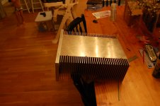
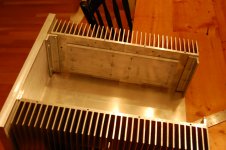
So, based on this, its not that my heatsink size is negatively affecting the dissipation of the fets,I am simply not utilizing it to its fullest potential. ANywho, here is my final build. Any pointers and advice welcomed. Andrew, have you tested your theory above with suitable equipment. I believe there is a fellow who has some imaging equipment and has started a thread about it. Will have to find it.
Attachments
Not having any problem with heat, but i can confirm that the blimey rule is very accurate. Nelson, we have been discussing the diode and the effect it has on the response of the amp. Are we correct that the diode only extends the amount of Class A/B power and has no effect on Class A bias levels.
- Status
- This old topic is closed. If you want to reopen this topic, contact a moderator using the "Report Post" button.
- Home
- Amplifiers
- Pass Labs
- My F5T V3 build