I bought this amp on ebay.It is low price and goid sounding.I think on of the best high power digital amps.Specialy because of the excellent infinion 2092 driver ic.But it is far away from Top high end sound.The treble bring not the dynamic and clearness of some other high end amps.But better than some 2000 Euro store amps.
L20D changed the inductor, the use of more 7 g23a inductance.
Can reduce the temperature. Reduce resistance. Increase the current.
Circuit diagram can reference IRAUDMP7S - 200. They are exactly the same.
I don't know why I log in BBS very slow.
It will take about 10 minutes. If there is anything not clear can email to me.
ljm_ljm@foxmail.com
I bought this amp on ebay.It is low price and goid sounding.I think on of the best high power digital amps.Specialy because of the excellent infinion 2092 driver ic.But it is far away from Top high end sound.The treble bring not the dynamic and clearness of some other high end amps.But better than some 2000 Euro store amps.
Read this , same chip , same FET's , a bit more expensive
")
Audio Research DSi200 Integrated Amplifier (TAS 204) | The Absolute Sound I am Curious about the Top High end sound system components you'r revering to is and did you compare the amps on the same speakers in an A/B setup ? Please let us know .
Cheers ,
Rens
L20D changed the inductor, the use of more 7 g23a inductance.
Can reduce the temperature. Reduce resistance. Increase the current.
Circuit diagram can reference IRAUDMP7S - 200. They are exactly the same.
I don't know why I log in BBS very slow.
It will take about 10 minutes. If there is anything not clear can email to me.
ljm_ljm@foxmail.com
How about the L15D, is it using the g23a ?
I´ve posted this request in the wrong forum probably (bazaar), so I try here again. (The thread seems deserted).
The modules (L15D) are working well, but when I have some signal on the input and no load on the output, then R30 (10Ohm 1W zobel resistor) starts to produce signs of smoke. There must be a hell of RF energy going into it.
This resistor is darn close to the power filter electrolytic.
Although this is no problem during regular use, there may be a problem when one of the dc protection modules cuts the load off. During start-up this happens regularly, but only for one or two seconds. Also, a cable might become faulty or somebody might unplug the speaker. There is no guarantee the load is there.
Has anybody observed this or knows alleviation to it?
I suppose that´s what R31, the 2k2 shunt for the load is there, but it seems not to work.
China does not respond to a direct contact.
Edit: a guy noticed (somewhere here) that this happens when a SMPS is used and not with a linear PSU
Thanks,
-helmut
Last edited:
looking at the L25D board, which has a 10 ohm 2 watt resistor in that location ... it's part of the output parasite dampener and connected to a small cap that connects to 0 volts as well as to the output signal. What's happening is that the parasitics are just slightly more lively than expected and trying to bust loose. The load its self is enough extra dampening to kill the parasites. You could a: replace with a resistor with double the power rating. b: add another resistor in parallel with it .. about 20 ohms and a cap in parallel with the one I just mentioned that is about half the size of the cap that is installed there. The first fix won't kill the parasite, but will absorb it. The second fix will probably kill the parasite so there will be little to nothing to absorb. ... You might check the values of the resistor and capacitor and verify that they are correct. This sort of suggests that the cap or resistor may be off.
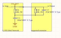
put the cap in series with the new resistor in stead of parallel .. in other words .. in parallel with the old cap. in other words again, just raise the current capacity of the filter/dampener they put there ..add about half the current capacity. 20 ohms and 47nf sounds about right I did that trick on some iraud200's that were bugging out just like you said, and the problem solved .. you don't have to solder this to the board, you can connect the rc network straight to the boards output-ground if you like. If 20/47 doesn't do it, you can add another full 10/100 .. the network will be like having your speaker load there for ultrasonics.
Thanks.
I will apply both measures, does no harm: double the original resistor in wattage and add an external network (to the screw terminals) with 22R/47nF.
(The PP caps for the voltage needed tend to be quite clumsy, so there is no space under the board.)
I ordered some 22R / 2W metal oxide resistors and some 47nF 330V class-X2 polypropylene caps. It will take a few days, but I will come back to report.
-h
Last edited:
Hi,
one of the bits I ordered is still on the way.
On some other thread a forum member had a good point too.
-h
http://www.diyaudio.com/forums/vendors-bazaar/180625-irs2092-iraudamp7s-irfi4019-38.html#post5039991
one of the bits I ordered is still on the way.
On some other thread a forum member had a good point too.
-h
http://www.diyaudio.com/forums/vendors-bazaar/180625-irs2092-iraudamp7s-irfi4019-38.html#post5039991
I changed all 10Ohm to 2x10Ohm/2W resistors and added the 22R/2W+47nF network as you recommended. The caps turned out smaller than expected and all fits snugly under the board.
I also ordered some 3n3/500V NP0 (C0G) ceramic caps which I fitted over the 1nF supply filter cap and, per recommendation from Bob Cordell´s book, across the output filter cap. This cannot harm.
The Zobels stay cool this time during off-load periods (don´t want to do an hour torture test). So this worked, thanks.
I kept my nose over the boards to see if anything goes up in smoke and I noticed, that after half an hour of loud music playing the board is getting hand-warm about where the control chip resides.
Cannot access from under, just on the top. Are they getting warm too, or is this a sign of something?
The amp ist very quiet, no hum, no hiss. Astounding.
-helmut
I also ordered some 3n3/500V NP0 (C0G) ceramic caps which I fitted over the 1nF supply filter cap and, per recommendation from Bob Cordell´s book, across the output filter cap. This cannot harm.
The Zobels stay cool this time during off-load periods (don´t want to do an hour torture test
). So this worked, thanks.I kept my nose over the boards to see if anything goes up in smoke and I noticed, that after half an hour of loud music playing the board is getting hand-warm about where the control chip resides.
Cannot access from under, just on the top. Are they getting warm too, or is this a sign of something?
The amp ist very quiet, no hum, no hiss. Astounding.
-helmut
Wahooo ... the control chip gets warm ... period .. it doesn't burn. However, on the boards that use it to drive transistors with higher gate charges, the control chip needs a heat sink. (iraud 200, Iraud350) I have run the L25D quite a while without heat sink on the control chip .. shouldn't be a problem.
Hi all
I have a concern about the input amplitude of the L25D and the L15D.
I will connect the Fiio D03K, that has 1,5V amplitude RCA out signal to L25D and L15D input. And the specs of this two says that the maximum imput amplitud is 3V.
I think that i cannot get the max amount of power this amps can produce because of that. So, what modification should i do? Add a 100K series resistor to the input current divider to get 200K Ohm? ¿?
Hi all
I have a concern about the input amplitude of the L25D and the L15D.
I will connect the Fiio D03K, that has 1,5V amplitude RCA out signal to L25D and L15D input. And the specs of this two says that the maximum imput amplitud is 3V.
I think that i cannot get the max amount of power this amps can produce because of that. So, what modification should i do? Add a 100K series resistor to the input current divider to get 200K Ohm? ¿?
Don't worry , You are correct with max input signal , but that doesn't mean the amps need that input voltage . From memory I recall that Voltage gain is 36 for L15D and 40 for L25D just as in the original Iraudamp7 design , so 1.5 Volt is plenty of signal to put both amps to full output power and even into clipping .
Cheers ,
Rens
Thank you very much Doc. You are from Australia, great! I will listen some Midnight Oil and Men at work.
The guy from EEVBlog is from Australia too. Very good videos.
Hi, I have buyed two L25d Boards 9 months ago and finaly finished my amp. Sadly i have trouble with one of the two Boards, after a few seconds one IRFB4020 burned. Looked like a used and already stresst one, so i replaced the transistor with a new IRFB4020 and tested the amp again. After ~ 1 hour the same transistor burned again. I replaced the IRFB4020 once again and did a careful test for 5 min. The Bord with the problem gets significant hot compared to the other one. I couldn't find any differences in the used parts between both boards, could the IRS2092 be damaged? I bought the Boards vom sep_store on ebay, vendor didn't respond to my question. I bought them 9 months ago, i guess i won't get any support. Any ideas whats wrong with my Board? I could add pictures next weekend if it helps. Sidefacts: I use one 500VA 53V transformer and one PSU Board with bridgerectifier and 4x 10mF 100V Caps (-->75V DC) for both Boards. So the Boards share Ground, Vcc and Vee. Some Guys here mentioned Noise in this config, could this be my fault? I would appreciate any help
Final Test for the L15D amp.
all is working now, except something on the modules seems to produce a lot of heat. After 1/2 hour of playing (I measured less than 1W per channel, which is loud!).
The heat sink remains almost cool. Touching the components vis-a-vis the controller (Oscon caps), they are uncomfortably hot. This can´t be a good thing on the long run.
I cannot access the controller when the modules are built in, but I suspect it is the source of trouble.
Is this normal, or what may be the reason for this heat?
Thanks,
-helmut
For the record.
I looked at the L15D boards with an infrared camera at low duty after 1/2 hour running time.
The dropper resistors heat up the boards considerably and are the cause for the hot electrolytics in their vicinity. They are by far the biggest source of heat there.
I mounted them with a spacer in a distance to the board so that convection has a better chance to cool them, particularly upon vertical board mounting as I did. Incidentally, this is how such components should be mounted anyway.
The boards stay much cooler now.
Simultaneously, as somebody stated hereabouts, the driver chips can be run with 12V just as perfect.
This brings power dissipation down in the drivers considerably without performance penalty.
I also spent a small heat sink which was probably redundant with the aforementioned measure.
The resisors are around 50°C, drivers around 40°C and the output coil too with low duty.
-h
For the record.
Simultaneously, as somebody stated hereabouts, the driver chips can be run with 12V just as perfect.
Hi Aquataur, can you explain how you did that mod (12v for driver)? Thanks.
- Home
- Amplifiers
- Class D
- My design L20D IRS2092+IRFI4020H 200W8R