not sure, but i'd be willing to look into a specific part if you have one to recommend.")
Haven't done any listening or even obtained one of these to try yet, just been browsing the Toshiba datasheets of late. On paper, the SSM6N24TU looks like a promising one. I'm looking mainly for good low-current transconductance when picking a part - this one is well above average with 250mS @ 10mA. (A bipolar would have 400mS at the same current, so FETs are catching up
). High transconductance means its able to keep the voltage at its source terminal fairly constant under variations in DAC output current. Its input capacitance is almost twice that of the IRF, but that's not really important for the common-gate stage.well what are simulations there for if not to get our hopes up?
I'll be well impressed if you manage it
Then I could use your method to sim my AD1955 output stage...yet more fixes
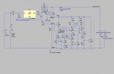
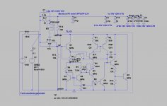
ok, new schematic.
1. uses ferrite beads.
2. uses the irlib9343 (to-220) as an output p-channel mosfet for the low-voltage shunt regulators. (thoughts?)
3. shunt regulator for i/v converters is left symmetrical. (if it ain't broke...)
4. reworked -5Vdc shunt regulator to use same shunt devices as +5Vdc shunt regulator. (awesome, thanks!)
5. kept the 10nF caps at the DAC inputs until new simulation results (or listening tests far in the future, whichever comes first) indicate otherwise.
regarding a more accurate simulation of the current output dacs, i might be able to hack something together within the week... if i'm lucky. so wish me luck!
~ brad.
ok, new schematic.
1. uses ferrite beads.
2. uses the irlib9343 (to-220) as an output p-channel mosfet for the low-voltage shunt regulators. (thoughts?)
3. shunt regulator for i/v converters is left symmetrical. (if it ain't broke...)
4. reworked -5Vdc shunt regulator to use same shunt devices as +5Vdc shunt regulator. (awesome, thanks!)
5. kept the 10nF caps at the DAC inputs until new simulation results (or listening tests far in the future, whichever comes first) indicate otherwise.
regarding a more accurate simulation of the current output dacs, i might be able to hack something together within the week... if i'm lucky.
so wish me luck!~ brad.
Attachments
Last edited:
Series-shunt reg results
Here are the results for the 5V/10mA shunt with simple ccs. It shows an LT1086 as that's provided in the LTSpice database, but I'm sure an LM317 would do just as well for a much lower price. As you'll be able to see from the plot - ripple rejection is not really circuit dependent, rather it'll be layout dependent. Perhaps this should be called a 'blameless reg' On second thoughts, its probably going to be a bit noisy for that title, based as it is on a bandgap ref.
Here are the results for the 5V/10mA shunt with simple ccs. It shows an LT1086 as that's provided in the LTSpice database, but I'm sure an LM317 would do just as well for a much lower price. As you'll be able to see from the plot - ripple rejection is not really circuit dependent, rather it'll be layout dependent. Perhaps this should be called a 'blameless reg'
On second thoughts, its probably going to be a bit noisy for that title, based as it is on a bandgap ref.Attachments
Last edited:
No rejection plots prior to this one as I've been only looking at getting a low impedance so only had a virtual ccs. Which ones would you like to see?
maybe that of the first schematic you posted? just to get a feel of the effect the '317 is having...
~ brad.
More plots
Here's the impedance plot of the shunt itself, when fed from the virtual ccs. -100dB figure here represents 10milliohms (100dB attenuation from 1k source).
The second plot shows the LT1086 (plus input RC) rejection - this is what's happening at the output pin of the reg (before the 125 ohm resistor).
Attachments
Preliminary conclusions...
Overall, I think aiming for a 10milliohm output impedance for the shunt was a bit too ambitious. The rejection when combined with a really cheap and simple LM317 based ccs is overkill and the low impedance above 10kHz was achieved with two fairly serious low ESR and one low ESL capacitor. These caps have bumped up the cost and the board area considerably. Knowing what I do now, on the next pass I'd aim for a much more modest shunt impedance - perhaps we don't need the FET shunt at all ?
To set this in context - 10milliohms is about the resistance of 10mm of 0.5mm width copper trace on a 1oz copper pcb. This is a very useful resource
BTW - like the new name 'blamegap reg'
Last edited:
... Knowing what I do now, on the next pass I'd aim for a much more modest shunt impedance - perhaps we don't need the FET shunt at all ?
very interesting results... i'd say that seems reasonable for such an application, though i'm sure there will always be those who say "it's never low enough..."
To set this in context - 10milliohms is about the resistance of 10mm of 0.5mm width copper trace on a 1oz copper pcb. This is a very useful resource
excellent, thanks for the link. that puts it in perspective...
like the new name 'blamegap reg'
perhaps i'll be cliché and say it just once in my life: i'll be here all week.
~ brad.
El cheapo shunt
OK, this is looking more practical now. Got rid of the bulky electrolytics and instead extended the low impedance out to 20MHz with an array of ceramics on the output. After all, I'd like to use this on my own DAC design so it needs to be 'digital capable' Impedance is <30milliohms across the band.
OK, this is looking more practical now. Got rid of the bulky electrolytics and instead extended the low impedance out to 20MHz with an array of ceramics on the output. After all, I'd like to use this on my own DAC design so it needs to be 'digital capable'
Impedance is <30milliohms across the band.Attachments
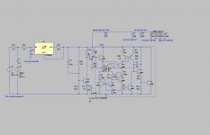
Electrolytic-free 1ppm reg
Here's today's little curio... After removing the shunt MOSFET I wondered if another use could be found for a transistor stage. It occured to me that more HF gain might suffice to eliminate the output electrolytic and use only (very cheap) ceramic capacitors. So here's the result - I've no idea whether it'll be too noisy in practice or even if it'll work... For those who think electrolytics mess up the sound, this is for you 
Here's today's little curio... After removing the shunt MOSFET I wondered if another use could be found for a transistor stage. It occured to me that more HF gain might suffice to eliminate the output electrolytic and use only (very cheap) ceramic capacitors. So here's the result - I've no idea whether it'll be too noisy in practice or even if it'll work...
For those who think electrolytics mess up the sound, this is for you Attachments
well, i have a question regarding simulating the current output of the dac. i got the idea of using current pulses, and i have a preliminary subcircuit, but i'm not sure if it's working...
my question is, if there is a 1k resistor in parallel with all the current pulses, shouldn't there already be a voltage across its nodes? or do i need to put some other resistor into the test circuit to measure the voltage out?
(the keen observer may notice this is a question borne out of a nonfunctional subcircuit... )
~ brad.
my question is, if there is a 1k resistor in parallel with all the current pulses, shouldn't there already be a voltage across its nodes? or do i need to put some other resistor into the test circuit to measure the voltage out?
(the keen observer may notice this is a question borne out of a nonfunctional subcircuit...
)~ brad.
success! of some kind...
ok, i've attached what i've got so far.
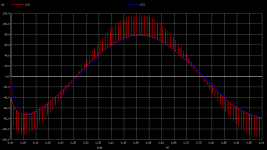
i've written a small, ridiculously buggy c program that outputs subcircuits for a given sample rate, output frequency (sinewave), and peak current output. i can then include the model file and use the subcircuit to simulate in spice. each step of the dac is a current pulse in spice. rise time is included in the subcircuit.
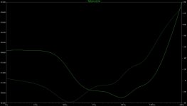
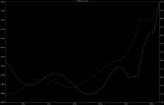
what i need is the expert opinions of others... is this an accurate representation or is more work needed? the red output is the raw output of the pulses, which for some reason is peaking... (is that natural?) the blue output is after a 1k+10nF LPF (fc=15khz).
i'm sure i can make it better, but i need to know if i'm barking up the right tree...
~ brad.
ok, i've attached what i've got so far.
i've written a small, ridiculously buggy c program that outputs subcircuits for a given sample rate, output frequency (sinewave), and peak current output. i can then include the model file and use the subcircuit to simulate in spice. each step of the dac is a current pulse in spice. rise time is included in the subcircuit.
what i need is the expert opinions of others... is this an accurate representation or is more work needed? the red output is the raw output of the pulses, which for some reason is peaking... (is that natural?) the blue output is after a 1k+10nF LPF (fc=15khz).
i'm sure i can make it better, but i need to know if i'm barking up the right tree...
~ brad.
Attachments
i've written a small, ridiculously buggy c program that outputs subcircuits for a given sample rate, output frequency (sinewave), and peak current output. i can then include the model file and use the subcircuit to simulate in spice. each step of the dac is a current pulse in spice. rise time is included in the subcircuit.
what i need is the expert opinions of others... is this an accurate representation or is more work needed? the red output is the raw output of the pulses, which for some reason is peaking... (is that natural?) the blue output is after a 1k+10nF LPF (fc=15khz).
i'm sure i can make it better, but i need to know if i'm barking up the right tree...
From your explanation, I haven't yet got a clear picture of what you're up to
The plot you've shown - is this the output of the I/V circuit, or the input to it? I'd also like to have a close up look at the response to a single pulse to understand why it might be peaking. Anyway, its a promising startIn the meantime, over the weekend I read this fascinating article about getting precise measurements from a DAC. Its the kind of piece that really 'floats my boat' with its fanatical attention to detail - dunno if it'll do anything for you
From your explanation, I haven't yet got a clear picture of what you're up to
sorry, more details... i have a c program which outputs a subckt like this:
Code:
.subckt pcm1704 iout gnd
rout iout gnd 1.0k
ip1 iout gnd pulse(0.000000ma 0.078484ma 0.000000us 200ns 0ns 10.416667us 1.000000ms)
ip2 iout gnd pulse(0.078484ma 0.156631ma 10.416667us 200ns 0ns 10.416667us 1.000000ms)
...
.ends pcm1704
my spice test file is just a real quick test:
Code:
* the sandbox.
.include test.mod
xdac 1 0 pcm1704
rlpf 1 2 1.0k
clpf 2 0 10nF
.tran 1ns 1ms 1ns 1ns
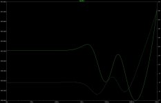
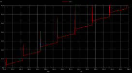
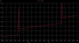
.endso there is no i/v conversion going on, so i guess the voltage measured is simply that due to the current pulses passing through the output impedance of the dac itself.
the attached pictures show the voltage at node 1, zoomed in.
these peaks don't seem natural, even without anything attached to the circuit... i'm considering an attempt at a better waveform using linear piecewise currents instead... will post a report soon.
In the meantime, over the weekend I read this fascinating article about getting precise measurements from a DAC. Its the kind of piece that really 'floats my boat' with its fanatical attention to detail - dunno if it'll do anything for you
reading the first paragraph seems it's off to a good start. i'll brew up some more coffee and have a read.
~ brad.
Attachments
Ah, now I've got a better understanding of your approach, thanks.
I'm curious why you've chosen a 0nS fall time in the pulses? (assuming I've got the right syntax for that statement). Might be the reason for the spikes. The DAC (as opposed to an idealised current source in Spice) wants to see a low output impedance, at the moment its looking into your LPF as its output.
I'm wondering whether it might be better to model the DAC as voltage pulses from a high-ish impedance rather than current pulses. This might more accurately reflect its R-2R internal structure. Then, if the output impedance isn't zero we'll get closer to modelling output compliance problems.
Since you've got a C program generating the individual samples, you could enhance the program to also create the particular code value that the DAC will be seeing (24 bits) and hence work out exactly what the output impedance would be from the resistor values in the R-2R network. But maybe that's a step too far... Would be jolly interesting though...
I'm curious why you've chosen a 0nS fall time in the pulses? (assuming I've got the right syntax for that statement). Might be the reason for the spikes. The DAC (as opposed to an idealised current source in Spice) wants to see a low output impedance, at the moment its looking into your LPF as its output.
I'm wondering whether it might be better to model the DAC as voltage pulses from a high-ish impedance rather than current pulses. This might more accurately reflect its R-2R internal structure. Then, if the output impedance isn't zero we'll get closer to modelling output compliance problems.
Since you've got a C program generating the individual samples, you could enhance the program to also create the particular code value that the DAC will be seeing (24 bits) and hence work out exactly what the output impedance would be from the resistor values in the R-2R network. But maybe that's a step too far...
Would be jolly interesting though...Final iteration of the 'blamegap reg'
I couldn't help trying out what happened when I added the extra AC gain stage to the 'enhanced' TL431 - that is, the one with the MOSFET shunt. The result was a worthwhile improvement, though the impedance was so good across the band it'll be a function of layout. After a little tweaking it managed an output impedance <1mohm from 20Hz - 100kHz (10mA current) still without using any electrolytics. This with a TL431, one MOSFET, an NPN transistor and a smattering of passives - BOM cost below 50cents.
I couldn't help trying out what happened when I added the extra AC gain stage to the 'enhanced' TL431 - that is, the one with the MOSFET shunt. The result was a worthwhile improvement, though the impedance was so good across the band it'll be a function of layout. After a little tweaking it managed an output impedance <1mohm from 20Hz - 100kHz (10mA current) still without using any electrolytics. This with a TL431, one MOSFET, an NPN transistor and a smattering of passives - BOM cost below 50cents.
This with a TL431, one MOSFET, an NPN transistor and a smattering of passives - BOM cost below 50cents.
very impressive. flat impedance across the band?
~ brad.
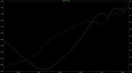
Blamegap impedance plot
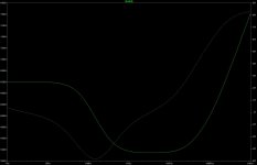
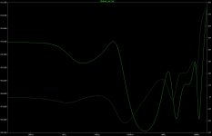
Not flat impedance across the band - as you can see - but minimum impedance in the ear's most sensitive region (amazing how I can think up justifications for almost any happenstance events...). 1mohm is -120dB on the left scale.
How's the DAC simulation coming along? I'm still struggling to understand inter-symbol interference in DACs...
Attachments
- Status
- This old topic is closed. If you want to reopen this topic, contact a moderator using the "Report Post" button.
- Home
- Source & Line
- Digital Line Level
- My Complete Solution DAC, RFC