This will work perfectly alright.
And it will give you more than 1 Ampere output (max 1.5A)
if you only have the needed HEATSINKS.
There is not much more you can change in your circuit,
that would give a better operation.
Eventually you can add some little resistor
that can be used to measure the current consumption.
Can be a 1 ohm 2/5watt resistor, placed between the bridge
and the LM317 input.
1 ampere gives 1 volt drop over that resistor.
/halo
Hi Deepanger,
It looks good to me, and having been involved right from the start when you first posted about the transformer query, I am glad to see it come to fruition.
Well done!
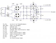
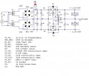
Don't be surprised if you loose a couple of volts or so of max voltage output under full load. It will depend on the Transformer rating and its regulation factor, but in converting from AC to DC the multiplier is 1.414. (24 X 1.414 = 34 volts) and there is a loss of say 1.2 volts caused by the diodes to take account of too.
It will entirely depend on the transformer's parameters, and your local voltage supply, but if everything is accounted for, you should see a minimum of about 33 volts with the transformer fully loaded, at the reg's *inputs*.
Of course, there will also be a small voltage drop through the regulators too, which will depend on current drawn and temperature to some extent.
You can check this from the maker's spec sheets which will usually indicate a ballpark figure, and often various dropout voltages, usually in the form of a graph, under varying operating conditions.
Regards,
It looks good to me, and having been involved right from the start when you first posted about the transformer query, I am glad to see it come to fruition.
Well done!
Don't be surprised if you loose a couple of volts or so of max voltage output under full load. It will depend on the Transformer rating and its regulation factor, but in converting from AC to DC the multiplier is 1.414. (24 X 1.414 = 34 volts) and there is a loss of say 1.2 volts caused by the diodes to take account of too.
It will entirely depend on the transformer's parameters, and your local voltage supply, but if everything is accounted for, you should see a minimum of about 33 volts with the transformer fully loaded, at the reg's *inputs*.
Of course, there will also be a small voltage drop through the regulators too, which will depend on current drawn and temperature to some extent.
You can check this from the maker's spec sheets which will usually indicate a ballpark figure, and often various dropout voltages, usually in the form of a graph, under varying operating conditions.
Regards,
deepanger said:really glad to hear ur comments..
but what about the fuse?
ive placed a 1A one due to some calc. but amnt sure of it...
what do u think?
Hi,
Apart from making some rudimentary calcs (like you have done) to get into the right ballpark with fuses, I rely on subsequent trial and error.
Fuses can blow in rather unexpected ways, I found years ago, and you have different characteristics with fuses, of course, to cope with different circumstances, like quick-blow, and time (or delay), or anti-surge, to cope with high switch-on loads.
Generally, with any new circuit, I will find the right area to work in, and then deliberately try the 'worst case' circumstances, to see if it will blow.
If it doesn't blow at all, I will try a lesser value until it does, and then go up in value a small amount, for the final choice.
This is the most practical way of arriving at the best overall result,
which will give safe protection, but not too many blown fuses which are an inconvenience.
Incidentally, for audio use, I don't use fuses at all, because they are not good for the 'sonics', but I will use circuit breakers instead after finding a suitable value (as indicated above) by experimenting with fuses first.
Regards,
Re: Final Schematic

A BIG, BIG problem is WHERE to put the LED.
It is this question that makes the GOLDEN EAR AUDIOPHILES (you know which ones I mean )
sleepless at night.
I would put it just after the rectifier.
Use one 33kohm(1/4watt) Resistor and a normal RED LED.
Put them in series from +36V to -36V
gives about 2 mA in the LED.
This will serve as an ON-indicator.
/halo - can NOT HEAR this LED - but here are people THAT COULD !!
- that's for sure
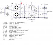
Now,deepanger said:here's the final schematic for anyone intersted..
but plz review it and post any corrections, recomm.,..etc
A BIG, BIG problem is WHERE to put the LED.
It is this question that makes the GOLDEN EAR AUDIOPHILES (you know which ones I mean
)sleepless at night.
I would put it just after the rectifier.
Use one 33kohm(1/4watt) Resistor and a normal RED LED.
Put them in series from +36V to -36V
gives about 2 mA in the LED.
This will serve as an ON-indicator.
/halo - can NOT HEAR this LED - but here are people THAT COULD !!
- that's for sure
Re: Re: Final Schematic
ive to know the resistance of the LED to calculate the other
resistor value. but ive tried to mesure it with my AVO but get nothing,imean bigger unknown value than 2megaohm!
so whats the LED resistance?
halojoy said:
Now,
A BIG, BIG problem is WHERE to put the LED.
It is this question that makes the GOLDEN EAR AUDIOPHILES (you know which ones I mean
sleepless at night.
I would put it just after the rectifier.
Use one 33kohm(1/4watt) Resistor and a normal RED LED.
Put them in series from +36V to -36V
gives about 2 mA in the LED.
This will serve as an ON-indicator.
/halo - can NOT HEAR this LED - but here are people THAT COULD !!
- that's for sure
ive to know the resistance of the LED to calculate the other
resistor value. but ive tried to mesure it with my AVO but get nothing,imean bigger unknown value than 2megaohm!
so whats the LED resistance?
I do not measure resistance of LED.
A LED is a diode. It has like a diode a typical voltage.
At some few mA (2-5mA) it is about 1.50-1.60 volt
over a Red LED.
I test it with diode-tester.
So if we put 72 volt over a 33kohm+LED
there is 72-1.5= 70.5V over the resistor. And 1.5V over LED.
70.5V/33k = 2.13 mA will flow.
/halo
A LED is a diode. It has like a diode a typical voltage.
At some few mA (2-5mA) it is about 1.50-1.60 volt
over a Red LED.
I test it with diode-tester.
So if we put 72 volt over a 33kohm+LED
there is 72-1.5= 70.5V over the resistor. And 1.5V over LED.
70.5V/33k = 2.13 mA will flow.
/halo
halojoy said:
At some few mA (2-5mA) it is about 1.50-1.60 volt
over a Red LED.
i wanted this!
thanx..
UrSv said:You might want to change the direction of that LED. I would also put it after the regulator so that you see when the regulator fails to no ouput.
sorry, i always ve a wrecked brain with those basics

btw icant place the LED after the reg. since the output volt. is
variable, in the same time ill know if something goes wrong from
the voltmeter..
what about the PCB? can i draw it myself?
thanks..
Attachments
I've been looking into buiding a simple powersupply as a first project. I've been thinking about a very similar design, except for one thing: why not keep the positive and negative supplies completely seperated? Shouldn't that give you the possibility of having two positive, two negative or one positive and one negative supply by connecting the right output pins with eachother?
Re: 0 to 30v/higher current
i dont know exactly what u mean, this simple ps. can give one +
and one - outputs or even 2 + , or 2 - outputs (by connecting the
load in reverse), or can be used to provide (+,0,-) for thos loads
that require it like power amps. as in here..
what r those transistors?!
hegestratos said:I've been looking into buiding a simple powersupply as a first project. I've been thinking about a very similar design, except for one thing: why not keep the positive and negative supplies completely seperated? Shouldn't that give you the possibility of having two positive, two negative or one positive and one negative supply by connecting the right output pins with eachother?
i dont know exactly what u mean, this simple ps. can give one +
and one - outputs or even 2 + , or 2 - outputs (by connecting the
load in reverse), or can be used to provide (+,0,-) for thos loads
that require it like power amps. as in here..
this s a current boost circuit?! i see it somewhere...jackinnj said:try this, pasting together from Nat Semi's website (I actually use this in a POOGE'd Heathkit IP27 power supply.)
what r those transistors?!
Re: Re: 0 to 30v/higher current
My thought is that now, you can't connect two loads on a positive potential with the return at the same potential, e.g., one at +12-0 and one at +5-0. If you keep the two supplies seperate from the start (provided your transformer has two _separate_ secondary windings), you can do all your design does and more. Yours would be like mine with two output pins connected already, whereas I can choose which two pins to connect (if I want two pins to be connected at all).
deepanger said:
i dont know exactly what u mean, this simple ps. can give one +
and one - outputs or even 2 + , or 2 - outputs (by connecting the
load in reverse), or can be used to provide (+,0,-) for thos loads
that require it like power amps. as in here..
My thought is that now, you can't connect two loads on a positive potential with the return at the same potential, e.g., one at +12-0 and one at +5-0. If you keep the two supplies seperate from the start (provided your transformer has two _separate_ secondary windings), you can do all your design does and more. Yours would be like mine with two output pins connected already, whereas I can choose which two pins to connect (if I want two pins to be connected at all).
I agree with Jackinnj - have a look at the Nat Semi datasheet: http://www.national.com/ds/LM/LM117.pdf
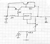
Paralleling regulators has it's complications as you have discovered. Adding a relatively simple current booster is the way to go. It works by measuring the current that goes into the regulator and then multiplies it and feeds it to the regulators output. Quite clever. Ignore the NS datasheet that says to use 3 LM195s in parallel - you can use a single beefy device.
Or find a higher power regulator. You may have trouble finding a -'ve version - but you don't need one. Read on...
I think Hegestratos has a good idea. You can simply build two identical and completely separate psus (both using LM317 - no need for LM337) and then just join the + and - outputs up as you desire. More flexible this way. Also means you can have the star ground of the circuit you are powering being elsewhere than the bench supply terminals.
I´m actually about to build the same power supply.
LM317/337 one for each rail but I chose the TO-3 case.
If the power dissipation doesn´t exceed about 20W I get 2A out which is all I need.
If you should decide for more current deepanger, just have a look into the datasheet and search for the "adjustable 4A regulator" where it shows how to properly parallel the LM317.
Pass transistors are of course a cheaper alternative but the circuit gets more tricky if you wanna keep the short ciruit protection of the regulator.
Regards
Jens
Jens - likes datasheets
traderbam said:I agree with Jackinnj - have a look at the Nat Semi datasheet: http://www.national.com/ds/LM/LM117.pdf
Paralleling regulators has it's complications as you have discovered. Adding a relatively simple current booster is the way to go. It works by measuring the current that goes into the regulator and then multiplies it and feeds it to the regulators output. Quite clever. Ignore the NS datasheet that says to use 3 LM195s in parallel - you can use a single beefy device.
Or find a higher power regulator. You may have trouble finding a -'ve version - but you don't need one. Read on...
I think Hegestratos has a good idea. You can simply build two identical and completely separate psus (both using LM317 - no need for LM337) and then just join the + and - outputs up as you desire. More flexible this way. Also means you can have the star ground of the circuit you are powering being elsewhere than the bench supply terminals.
idont know if u noticed that am paralleling the 2 transformers together just to get 24-0-24 secondries since icant get a trans.
in here rated as the same sec. volts and current.. so icant simply
build a 2 separated PSUs as u suggested..
and about getting more current using the pass transistor as u
mentioned ,ill need to get a higher rated trans. and amnt sure i
can but ill try .. and i think ineed to add more filter capacitors
right?
- Status
- This old topic is closed. If you want to reopen this topic, contact a moderator using the "Report Post" button.
- Home
- Amplifiers
- Solid State
- My bench power supply..