Re: the resistor before the regulator
well, idont ve that much experience working with discrete components so ican build my own regulator , thats why i started
to use the common LM317 reg. , ican substitute it with a more
current handling one like the LM150 ,LM138...etc. when they are
available in here..
can u explain more the oscillation prob.?! anyway to eleminate it ? i find it gonna be more easy if ican find away to parallel em than to do build the regs. from scratch...
and what about the thermal resistor i asked about before, anyone
has any ideas what it really does..?
sorry for my many ques. but we are almost near the end!!
thanks..
Christer said:I agree with jackinnij, if you need to go near or above the limits
of what a 317 can handle, don't use it, but do you own regulator.
You might find the following handbook from On Semi helpful,
even though it is about IC regulators, it will teach you some
of the basic theory of voltage regulators.
http://www.onsemi.com/pub/Collateral/HB206-D.PDF
jackinnj said:is current sense for the regulator and pass transistor combo -- as the current drawn increases (and the voltage drop across the transistor increases) it reduces the amount of work which the regulator has to perform and shifts this function to the transistor.
if you tie two LM317's together as described you can get some nice oscillations -- in fact, getting an LM317 to oscillate isn't difficult at all. At any rate, it's using a more expnesive part to do a less expensive job.
well, idont ve that much experience working with discrete components so ican build my own regulator , thats why i started
to use the common LM317 reg. , ican substitute it with a more
current handling one like the LM150 ,LM138...etc. when they are
available in here..
can u explain more the oscillation prob.?! anyway to eleminate it ? i find it gonna be more easy if ican find away to parallel em than to do build the regs. from scratch...
and what about the thermal resistor i asked about before, anyone
has any ideas what it really does..?
sorry for my many ques. but we are almost near the end!!
thanks..
Right you are!
Bobken,
Right you are - the bypass cap improves ripple rejection, not line regulation.
deepanger:
The 0.1 Ohm resistor at the output is only needed if you are paralleling the 317's. It is to stop the paralleled regulators from 'fighting' for control of the output voltage.
Bobken,
Right you are - the bypass cap improves ripple rejection, not line regulation.
deepanger:
The 0.1 Ohm resistor at the output is only needed if you are paralleling the 317's. It is to stop the paralleled regulators from 'fighting' for control of the output voltage.
Re: Right you are!
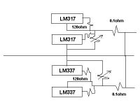
well, if i paralled the LM3x7 for both + and - rails and placing those 0.1 ohm resis. the schematic will be like this:
am i right??
Sud said:Bobken,
Right you are - the bypass cap improves ripple rejection, not line regulation.
deepanger:
The 0.1 Ohm resistor at the output is only needed if you are paralleling the 317's. It is to stop the paralleled regulators from 'fighting' for control of the output voltage.
well, if i paralled the LM3x7 for both + and - rails and placing those 0.1 ohm resis. the schematic will be like this:
am i right??
Attachments
deepanger said:hey good guys..dont leave me in the middle of it!!
ineed someone just to check the previous diagram plz..
Hi,
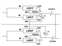
Unfortunately, it is not clear from your diagram which lead is which, and at a quick look it doesn't seem to be very consistent.
Whatever you intend here, each similar lead from the same polarity device must be attached in an 'identical' way for the two devices to be truly in parallel.
Conventionally, when using a 'box' to indicate a 3 terminal reg,
it is shown with the input at the left side, the output at the right side, and the adjust (or ground for fixed regs) lead at the bottom and in the middle.
If you have used this conventional arrangement in your diagram, it will not be correct, but you show no labels to indicate which is which.
Regards,
Hi,
As I suspected, this is not quite correct.
Bear in mind that the 'adjust' resistor needs to run between the adjust pins and ground.
If the unmarked horizontal line is ground, it looks like with the LM317 that this upper 'adjust' resistor goes between the adjust pin of the upper 317 and the adjust pin of the lower 317, and then the connection goes via ground (if this a *connection* where it crosses the horizontal line?), and/or then on to the 337's adjust pin.
Regards,
bench
Bob is right, the top and bottom regulators don't do anything. You need to connect ALL regs as he said: all need to be set up for the correct output voltage independently. Then, for say the pos pair, each output must go via a separate 0.1 Ohm to the final pos output. Same for the neg pair. It really is much simpler than you seem to think.
Jan Didden
deepanger said:i think its right now!!
"this s for the pos. side only of course"
Hi,
Yes, that looks fine now, but I cannot vouch for the 0.1R resistors at the outputs as they were not the result of my recommendation. But this is what some of the other posters have said, and I have no reason to doubt that it is a good thing.
Regards,
Bobken said:
Hi,
Yes, that looks fine now, but I cannot vouch for the 0.1R resistors at the outputs as they were not the result of my recommendation. But this is what some of the other posters have said, and I have no reason to doubt that it is a good thing.
Regards,
many thanks to u all..
ill post the final schematic soon after some experiments of it
may god survive me!

thanks again..
deepanger said:
many thanks to u all..
ill post the final schematic soon after some experiments of it
may god survive me!
thanks again..
Well done Deepanger, you have got there in the end, and perseverance IMO is important in this game.
Regards from Deeprelief!
 (only joking!)
hi again..
ive build the pos. side of the schematic with 2 paralleled LM317s
the output volt. is ok (from 1.3 upto 35V noload) ,when the circuit
is loaded providing about 13V and about 0.5A, one of the reg.
gets too hot that it cant be touched for 2sec. while the other reg. is so cool ...
...
dont know its obvious that the 2regs. dont share equal amounts
of current, ive swapped em so ican guarantee that theres nothing
wrong with the wiring, but the same reg. is so hot and the other
is cool, i tested each one alone, both working fine "albeit they
gets really hot caz of the dissipation (35-13 * 0.5 = 11watt)"
any ideas about whats wrong?
ive build the pos. side of the schematic with 2 paralleled LM317s
the output volt. is ok (from 1.3 upto 35V noload) ,when the circuit
is loaded providing about 13V and about 0.5A, one of the reg.
gets too hot that it cant be touched for 2sec. while the other reg. is so cool
...dont know its obvious that the 2regs. dont share equal amounts
of current, ive swapped em so ican guarantee that theres nothing
wrong with the wiring, but the same reg. is so hot and the other
is cool, i tested each one alone, both working fine "albeit they
gets really hot caz of the dissipation (35-13 * 0.5 = 11watt)"
any ideas about whats wrong?
Re; 2 parallel reg - one gets much hotter
This is just a wild guess.
I understand volage reulators are little more than a very speacialized transistor plus a couple of other components. Assuming I'm right (something that actually turns out to be the case occasionally), it is often the case the two transistors even from the same batch have wildly different values though still with in nominal min/max spec. In your case perhaps one piece has an input impedance (resistance actually since this is all DC) at the high end of the acceptable range and the other at the low end. You could try to equalize this by making a inserting a voltage divider made up of two low value resistors between them and the current source. You can just experiment to find the values or if you can measur the impedance of each and calculate the resistor values.
I would also mount them to opposite sides of the same heatsink. To the extent that their performance is affected by temperature, it would be good to try to equalize that -- I think ?
Re: Re; 2 parallel reg - one gets much hotter
yea, you r right.. one of the regulators (from radioshack) is the
one which always gets hot when the same input is feeded to both
(the other one is from another local shop), by placing low value resistor before the input of the radioshack one i notice the heat
dissip. is nearly shared bet. the two.
ill get a new one from radioshack so maybe it gonna be within the
same range of input impedance and it works..
ill inform u as soon as i test it..
thanks.
sam9 said:This is just a wild guess.
I understand volage reulators are little more than a very speacialized transistor plus a couple of other components. Assuming I'm right (something that actually turns out to be the case occasionally), it is often the case the two transistors even from the same batch have wildly different values though still with in nominal min/max spec. In your case perhaps one piece has an input impedance (resistance actually since this is all DC) at the high end of the acceptable range and the other at the low end. You could try to equalize this by making a inserting a voltage divider made up of two low value resistors between them and the current source. You can just experiment to find the values or if you can measur the impedance of each and calculate the resistor values.
I would also mount them to opposite sides of the same heatsink. To the extent that their performance is affected by temperature, it would be good to try to equalize that -- I think ?
yea, you r right.. one of the regulators (from radioshack) is the
one which always gets hot when the same input is feeded to both
(the other one is from another local shop), by placing low value resistor before the input of the radioshack one i notice the heat
dissip. is nearly shared bet. the two.
ill get a new one from radioshack so maybe it gonna be within the
same range of input impedance and it works..
ill inform u as soon as i test it..
thanks.
bench
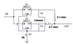
Revieuwing the schematic I see you are running the two regs from the same ref (common 5k pot). Since they will never be exactly the same, the outputs will not be exactly the same, and one will supply the bulk of the current. The normal cure is using low value resistors as shown. Maybe you need more here (try .5 Ohms Bob?). You can also try to supply the ref from a single 240 Ohms from the final output instaed of from each reg output.
Jan Didden
Re: bench
Jan,
I honestly cannot say here since (as you may recall from some of our earlier discourses) I will only (usually) speak from experience, and, although I would like to help, I don't have any personal experience of paralleling 3 term regs. (Possibly like yourself, I don't like them or use them for audio, at all, but this is different in a bench PS!)
However, your idea seems a good one to try, and I am sure there is little harm in trying out some changes like you suggest.
Otherwise, I am sure I have come across many suggestions elsewhere on the Internet and possibly even in manufacturers' spec sheets (also now available on the 'net), which, as you know frequently have applications advice which may well include this topic, and I would suggest a search to be certain.
Regards,
janneman said:Revieuwing the schematic I see you are running the two regs from the same ref (common 5k pot). Since they will never be exactly the same, the outputs will not be exactly the same, and one will supply the bulk of the current. The normal cure is using low value resistors as shown. Maybe you need more here (try .5 Ohms Bob?). You can also try to supply the ref from a single 240 Ohms from the final output instaed of from each reg output.
Jan Didden
Jan,
I honestly cannot say here since (as you may recall from some of our earlier discourses) I will only (usually) speak from experience, and, although I would like to help, I don't have any personal experience of paralleling 3 term regs. (Possibly like yourself, I don't like them or use them for audio, at all, but this is different in a bench PS!)
However, your idea seems a good one to try, and I am sure there is little harm in trying out some changes like you suggest.
Otherwise, I am sure I have come across many suggestions elsewhere on the Internet and possibly even in manufacturers' spec sheets (also now available on the 'net), which, as you know frequently have applications advice which may well include this topic, and I would suggest a search to be certain.
Regards,
Re: bench
u mean those small 0.1ohm at the output of each reg.??
all idid is to place some diff. value resistors b4 the input of that
reg. that gets too hot, by the way am working now with two
identical regs. (both from radioshack from the same manufac.)
but the same prob. happens ,
anyway are there any guaranteed methode so i can make the 2regs share the same amounts of current even using a more complex methode?
janneman said:Revieuwing the schematic I see you are running the two regs from the same ref (common 5k pot). Since they will never be exactly the same, the outputs will not be exactly the same, and one will supply the bulk of the current. The normal cure is using low value resistors as shown. Maybe you need more here (try .5 Ohms Bob?). You can also try to supply the ref from a single 240 Ohms from the final output instaed of from each reg output.
Jan Didden
u mean those small 0.1ohm at the output of each reg.??
all idid is to place some diff. value resistors b4 the input of that
reg. that gets too hot, by the way am working now with two
identical regs. (both from radioshack from the same manufac.)
but the same prob. happens ,
anyway are there any guaranteed methode so i can make the 2regs share the same amounts of current even using a more complex methode?
I just finished up a 0-30V 0-10A bench psu. It used IRFP240's and OPA541 HV opamps. I will have schematics whenever I get some spare time. It works fairly well and can even take a screwdriver across the output with no damage. The display just shows 0V and current equal to the current limit.
Darrell Harmon
Darrell Harmon
- Status
- This old topic is closed. If you want to reopen this topic, contact a moderator using the "Report Post" button.
- Home
- Amplifiers
- Solid State
- My bench power supply..