new thread
<quote>
Maybe we should also start a new RevA/RevC consdensed thread.
</quote>
That's right! In the beginning of the thread some condensed information would be useful:
- schematic, pcb and Mauro's pdf
- Differences between Rev A and Rev C (technical and audible)
- Some special hints for mounting the kids, e.g. that the zeners and the power resistors should not be mounted on the pcb - as I did for my first cannel not remembering the old post or the min/max specs of a trafo.
A thread like that would be very useful for the folks building the amp themselves or building it with the (really great) kit of russ and brian.
Posts like "where to buy which parts in any part of the world" should not be posted there becaus of the overview.
Have a nice day
floric
P.S.:
Russ, Brian, thanks for the really gool labeled kits!
Re: X-Calibre
I have to quote myself. Enough said
Well the artwork went in today so look out for the new thread for X-Calibre. Minus the measurements seeing that I do not have the equipment (or the skill at that)
My and others ears will tell them if they hate it of love it.
I did pose the question a couple of hundred posts back as to what he sees as the ultimate system. I still would like to know but this was just my attempt to stir it up a bit and gave the people what they have been wondering about
Thanks Mauro for a great design. you really put the big expensive stuff to shame with this design
rudi said:
I might have to open a new thread for this if i am to pursue it
Please take note. i am not saying that the resistor/zener sounds bad, I actually like it. We are just pushing the boundaries here and I for one like the regulators better
I have to quote myself. Enough said
Well the artwork went in today so look out for the new thread for X-Calibre. Minus the measurements seeing that I do not have the equipment (or the skill at that)
My and others ears will tell them if they hate it of love it.
I did pose the question a couple of hundred posts back as to what he sees as the ultimate system. I still would like to know but this was just my attempt to stir it up a bit and gave the people what they have been wondering about
Thanks Mauro for a great design. you really put the big expensive stuff to shame with this design
Another Newbie Rev C Success Story
I have just completed the first DIY project I have attempted since a Hafler Dynakit in the 70's, and was frankly amazed when it powered up and work perfectly from the start.
I ended up using an old SCSI hard drive case I had been holding on to as a chassis, which makes for a unique appearance; but everything fit and it runs quite cool with the oversized heatsink on the front.
Here's a link to a photo:
Link
I can hear just a bit of 60 cycle through the speakers if I put my ear against them. It's much too low to make a difference in normal listening, but I wonder if moving the transformer a bit or putting in some shielding panels might eliminate it.
I have put the MyRev in my system in place of a 45wpc PrimaLuna Prologue Two tube integrated running ACI Sapphire XL speakers. I will let it totally burn in before doing any serious listening - but even initial impressions indicate that it is holding its own in terms of both musicality and detail. It is a much more coherent and musical presentation than I have heard on a solid state amp before. Bravo Bravo Mauro! As well as sincere thanks to Brian and Russ whose kit and advice made it painless.
.......Well- trying to find some of the information you need to build it right in this megathread was sometimes painful- but I learned a lot in the process.
I would like to see the mods in a separate thread - I enjoy reading about them and may try some- but it is confusing when posts alternate topics.
I think Floric made some great suggestions for a condensed information post to make building simpler for new folks. I would also like to see a simplified synopsis of what makes this design different from a gain clone. I know the MyRevs are a unique approach but I do not really understand why.
Thanks again all---- now on to the pre-amp thread.
George
Hi George,
Thanks for your kind remarks.")
You slight humm is very likely because your signal wire run right next to the trafo, it would be better if you could keep them away, but in your case I am not sure how you could do that.
Its very good case resuse BTW.
Good work!

Cheers!
Russ
Thanks for your kind remarks.
You slight humm is very likely because your signal wire run right next to the trafo, it would be better if you could keep them away, but in your case I am not sure how you could do that.
Its very good case resuse BTW.
Good work!
Cheers!
Russ
"You slight humm is very likely because your signal wire run right next to the trafo, it would be better if you could keep them away, but in your case I am not sure how you could do that."
Dead on...
Slide some metal braiding over the signal wires and ground ONE end to the chassis.
Dead on...
Slide some metal braiding over the signal wires and ground ONE end to the chassis.
Hi groch, looking to the picture I've seen that your heatsink is probably "floating". In my "My_ref" I can hear some noise if I connect the chassis only to main earth so, try to connect the chassis in the same point to one of the power GND. To brake the earth loop I've used an RC network, 100ohm/3W non inductive and 1000pF ceramic disk 2000V. Be sure to provide a good connection between chassis and the heatsink.
Now my amp is dead quiet...
Another thing. Try to put some space between output cables and signal cable. The current that pass in the output power cables could probably induce some noise into the input. This is not the reason of your noise pick up in my opinion, however it is a good habit to leave the signal cable far from high currents...
Mark
Humming along
Thanks for all of the advice on the hum issue. Under normal circumstances it is quite low- within the range of some commercial amps I have owned.
I have noticed that if I disconnect the signal inputs from my pre-amp the hum greatly increases - not speaker damaging loud- but clearly audible across the room.
I assume this is not normal and will try some of the suggested fixes.
The chassis is grounded to the mains ground - and the heatsink is attached by 3 metal screws to the unpainted chassis - my MM confirms 0 resistance.
The - amp boards are not connected to chassis ground. I am new enough at this that the connection of the boards to the transformer was itself confusing to me so before I ground the boards I want to be sure I am doing it right.
The transformer leads are connected to PGND and AC1 on both boards. I assume that is right because it worked. (what is AC2 for?). If I understand Mark's suggestions I should connect the PGND on both amps to the chassis ground through 100 ohm/3@ resistor/1000pF capacitors - I assume that the transformer leads also remain connected to PGND. I will try it if I understand it right and it will not initialize the smoke generators.
With the narrow dimensions of the chassis the better input shielding should help a lot. I had braided the input wires - but assume that providing a shield- or using a shielded microphone cable - and tieing the shield to chassis ground would be far more effective. I have some old patch cords that have 2 signal wires and a copper shield I could used for this.
Finally, the chassis would allow me to move the transformer about an inch towards the left side of the chassis- that would be a lot of work at this stage and I don't want to do it unless you think that would make a difference.
Thanks in advance for your confirmation and advice.
George
Re: Humming along
Wow, no that is not right at all. Your trafo sould have either a center tap or dual scondaries which should be connected in series and a wire taken for the point at which that connection is made as a new "ceneter tap". You then take the too ends of the transformer secondary (+AC and -AC that is they are in opposite phase) you then run two wires from each or those and connect one wire from one pair to AC1 on one board and the other to AC1 on the other board. You take the other secondary wire and connect two wires to it as well and run one to AC2 on one board and AC2 on the other. You then take two wires and connect them to the center tap wire and that is your power ground, you connect one wire to GND on one board and then take the other to the GND on the second board.
I am amazed your amp is not
 dead!
dead!
Please fix it ASAP!!!
You do not connect the GND on the PCB to anything at all, except possibly the HS, but only if it is isolated from mains GND by some means(electrical or physical). Mains GND should only be connected to the case, and isolated from everything else.
Cheers!
Russ
groch said:The transformer leads are connected to PGND and AC1 on both boards. I assume that is right because it worked. (what is AC2 for?).
Wow, no that is not right at all. Your trafo sould have either a center tap or dual scondaries which should be connected in series and a wire taken for the point at which that connection is made as a new "ceneter tap". You then take the too ends of the transformer secondary (+AC and -AC that is they are in opposite phase) you then run two wires from each or those and connect one wire from one pair to AC1 on one board and the other to AC1 on the other board. You take the other secondary wire and connect two wires to it as well and run one to AC2 on one board and AC2 on the other. You then take two wires and connect them to the center tap wire and that is your power ground, you connect one wire to GND on one board and then take the other to the GND on the second board.
I am amazed your amp is not
dead!Please fix it ASAP!!!
You do not connect the GND on the PCB to anything at all, except possibly the HS, but only if it is isolated from mains GND by some means(electrical or physical). Mains GND should only be connected to the case, and isolated from everything else.
Cheers!
Russ
Woooo
I think your amp is working with only an half wave...and do you say that it works???? Strange...
The pwd supply is a dual one, you have to provide 24V-0-24V and this is the reason of Ac1 and AC2.
Well, this is a fine example of monoblock "no-sense" because split the rails using a common trafo is a non-sense...Mauro's original pcb is better in this case IMHO. So, you must connect the trafo as Russ said. The noise you hear is due to an oscillation and probably the reason is the heatsink that is "floating".
A question...are the input chinch insulated from the chassis? You have to leave them insulated. And the L and R signal gnd between them too.
Then for the gnd connection. You have to connect the case to the main EARTH for safety, but this is not enough because the floating heatsink potential makes the 3886 to oscillate.
Because you have a single trafo you can simply connect one of the two PWR GND connector to the case, in the same point you connect the earth and using an rc network to break the earth loop. In this way you'll use the chassis to shield RF signal and you provide the right potential to the heatsink.
I (and not only me) use this solution. And Mauro, I think, can agree with this idea. So answer and repeat every step you have to do to have the right gnd/earth connection of the case...in this way we'll be able to understand what you're doing
Mark
Russ-
I am sure you are correct- it is shut down- but it sounded great.
I am using an Avel Y236801 that has, I believe dual secondaries rated at 25v when connected to 115AC.
Their wiring options are shown here: http://avellindberg.com/images/misc/tech notes/ps_configurations.jpg
I was trying to use the connection diagram listed as "standard dual primary" as it looked like that would give me the right voltage and provide independent supplys for each board. Blue and violet are both connected to one of the AC mains , and Brn/Gray to the other. The outputs were as described in the previous post.
I started to try to repeat back to you using my color codes exactly what you are telling me to do - but got confused when you talk about a center tap wire and also figure that the only reason things worked is that I must have the 115v input wires connected wrong as well.
It would really help if someone would go through this using my color codes before I do fry something. Thanks again in advance.
George
Brian-
As a new poster my messages are delayed, but I think your diagram clears things up.
I have modified it to match my color scheme I think
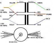
If I interprete things right, my AC primary inputs are fine as they are. Secondary Black goes to both boards AC1s, Blue goes to both boards AC2s, and the red/brown junction goes to both PGNDs.
Please confirm before I solder - also - please that my Avel transformer is the right rating - that is, this amended hookup will result in 25 volt output given the Y236801s standard 25v output ratings.
Thanks in advance.
George
As a new poster my messages are delayed, but I think your diagram clears things up.
I have modified it to match my color scheme I think
An externally hosted image should be here but it was not working when we last tested it.
If I interprete things right, my AC primary inputs are fine as they are. Secondary Black goes to both boards AC1s, Blue goes to both boards AC2s, and the red/brown junction goes to both PGNDs.
Please confirm before I solder - also - please that my Avel transformer is the right rating - that is, this amended hookup will result in 25 volt output given the Y236801s standard 25v output ratings.
Thanks in advance.
George
There is a problem with the way you have it stated...
On your trafo, BLUE is a primary and Yellow is a secondary.
Here's the picture with your trafo colors
[EDIT]: Looks like your picture was wrong but text description was wrong, probably confusion due to the colors not matching the words in the pic. I think you have it though.
On your trafo, BLUE is a primary and Yellow is a secondary.
Here's the picture with your trafo colors
[EDIT]: Looks like your picture was wrong but text description was wrong, probably confusion due to the colors not matching the words in the pic. I think you have it though.
Attachments
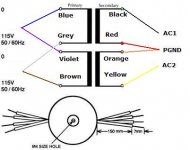
Disconnect the trafo from the boards. Then try to connect the secondary as Brian said...don't connect to the boards, you have to control the tensions on the secondary before, just to be sure.
You have to find something near 50/55V (remember...there is no load connected) between yellow and black and 25/28V between the center tap and the black/yellow.
If you find everything ok then connect all. Do not connect the Pwr Gnd to the chassis again. Try the amp and if you'll find some noise, then you'll have to try to connect the case to one of the two pwr gnd.
Mark
groch said:
Their wiring options are shown here: http://avellindberg.com/images/misc/tech notes/ps_configurations.jpg
Hi Groch for the secondaries use the wiring diagram which is on the lower right hand corner of the image you have above. Only for the secondaries.
You will then run two wires(one for each board) from the black lead to AC1 on each of the boards.
You then will run two wires(one for each board) from the RED/ORANGE(which should be joined) to GND on each board.
You then will run two wires(one for each board) from the yellow lead to AC2 on each of the boards.
Wire the primary to you mains as shown in the diagram on the top left that is join the blue and voilet, and connect them to mains hot. Join grey and brown and connect them to mains neutral. It is not critical which mains lead goes to which pair. But it is critical that you join the trafo pairs correctly.
Don't forget to use a fuse (I am sure you already had) I would use a 2-4 amp fuse.
Brian's diagram looks right on.
Cheers!
Russ
- Home
- Amplifiers
- Chip Amps
- My "audiophile" LM3886 approach