A To126 transistor case has a hole large enough to take a 3mm diameter fixing.The Caddock resistor is a TO-126 case and the hole size is 2.39mm +/-0.1mm so a metric M2 screw would fit.
If the resistor has a smaller hole then it is not the same as a To126 transistor package.
For a 2.39mm diameter hole you will find that a 2-56 and a 2-64 thread will pass through.
You will find that a 4-40 thread will not pass through.
An 8BA thread will pass through.
That gives you a few options.
If the hole is at max tolerance, i.e. 2.49mm you should find that an M2.5 will pass through. The thread crests are slightly smaller than the nominal thread size.
Last edited:
@atupi - that is what I've been looking for (wondering about).
I found an M2 bolt, washer and nut at a small hardware store. Spent last night "modifying" the heatsinks to fit and mounted them. Going out of town for the weekend, but hope to apply some voltage next week and check my work on the bench.
Thanks for all the replies - kept me from making any mistakes.
USofA stock metric screws !
We are "slowly" moving more to metric, but they are hard to find in smaller sizes. Thanks for jumping in on the thread.
A To126 transistor case has a hole large enough to take a 3mm diameter fixing.
If the resistor has a smaller hole then it is not the same as a To126 transistor package.
Caddock identifies the package as a TO-126 style. It does have a smaller hole than a transistor package. The numbers I quoted for diameter are from the Caddock datasheet.
You should do a bit more in interpreting that datasheet.Bill_P you were exactly right M2 fits perfect, also shows it only does 1.5w w/o a heatsink at 25C, so better safe than sorry.
When used without a heatsink upto the lower rated power the resistor will be operating at it's maximum temperature. That is likely to be over 100degreeC internally.
Adopting the heatsink but at the lower dissipation results in a much cooler running resistor. There should be sufficient detail in the datasheet to let you work out temperatures for both with and without a heatsink.
It would be instructive to go through the simulation/calculation and predict the final operating temperatures.
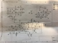
My "audiophile" LM3886 approach
I agree Andrew, but you just jumped WAY Over my head. I don't know the power dissipation of the resistor to start the calculation, nor enough about spec sheets to be able to interpret the data. I assume the designer is knowledgeable enough to suggest an adequate heatsink.
I agree Andrew, but you just jumped WAY Over my head. I don't know the power dissipation of the resistor to start the calculation, nor enough about spec sheets to be able to interpret the data. I assume the designer is knowledgeable enough to suggest an adequate heatsink.
My experience of chip amps is very poor.
I built my first one on an electronics course in 1980.
I think it was something like LM386 ? small wattage chip amp.
There were about a dozen of us on the course and everyone either blew up or got red hot.
Since then I have built a TDA7294 amp and it oscillated badly.
I had to put a 1000pf across inverting and non inverting inputs to tame it.
I have read up a bit on chip amp projects and found they are very fussy about decoupling and pcb layout.
My feedback resistor was quite a long way from TDA7294 and so was my decoupling. If the feedback resistor has long tracks then the inductance of them slows the feedback to the non inverting input and causes the output to overshoot.
I finally got everything together and did some voltage tests. Both boards were within 0.05 volts on all tests. The LM3886TF's are not installed yet.
Toroid (no load) - 29.56 and 29.53
LM318 (no load) -
pin 4 = -12.31
pin 7 = 12.23
LM3886 (no load)
pin 1 = 40.2
pin 4 = -40.2
pin 5 = 40.2
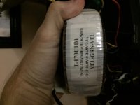
The toroidal is rated at 26.7-0-26.7, but apparently is a little higher at 29.5. So the final voltage to the LM3886 will be higher than I expected, instead of 38Vdc I'm getting 40Vdc. I plan to run 8 ohm speakers (very easy load) and be a desktop system, so fairly low volume. Am I safe using this Toroidal at least for a few weeks to make sure the build is worth spending $$$ on a new toiroidal?
Heatsink should be enough - it's 8"L x 2-1/2" W and 2-1/2" serrated fins of anodized alumninum. I am mounting both chips to this heatsink, about 4 inches apart.
Toroid (no load) - 29.56 and 29.53
LM318 (no load) -
pin 4 = -12.31
pin 7 = 12.23
LM3886 (no load)
pin 1 = 40.2
pin 4 = -40.2
pin 5 = 40.2
The toroidal is rated at 26.7-0-26.7, but apparently is a little higher at 29.5. So the final voltage to the LM3886 will be higher than I expected, instead of 38Vdc I'm getting 40Vdc. I plan to run 8 ohm speakers (very easy load) and be a desktop system, so fairly low volume. Am I safe using this Toroidal at least for a few weeks to make sure the build is worth spending $$$ on a new toiroidal?
Heatsink should be enough - it's 8"L x 2-1/2" W and 2-1/2" serrated fins of anodized alumninum. I am mounting both chips to this heatsink, about 4 inches apart.
It will drop but that transformer is not quite suitable for the lm3886 , your chip will overheat , your amp will start clipping right away so I think you need to drop
at least 5 volts each rail, you could rewire the transformer or you could use an voltage regulator circuit, a little bit of heat dissipated there, or you could trade with someone. I think I have some. What transformer is this?va?
If you would use it with 16-32 ohms speakers , it might be good.
at least 5 volts each rail, you could rewire the transformer or you could use an voltage regulator circuit, a little bit of heat dissipated there, or you could trade with someone. I think I have some. What transformer is this?va?
If you would use it with 16-32 ohms speakers , it might be good.
Last edited:
Good point(s).
Could you point me to a good adjustable voltage converter (AC) or describe how I could use zener's/diodes or resistors to drop the AC voltage by 4-5 volts? I'm a beginner, but know electricity safety and experienced with a DMM and able to following a diagram/instructions. Just hoping to "test" this before comitting to $50 for a new toroidal.
Could you point me to a good adjustable voltage converter (AC) or describe how I could use zener's/diodes or resistors to drop the AC voltage by 4-5 volts? I'm a beginner, but know electricity safety and experienced with a DMM and able to following a diagram/instructions. Just hoping to "test" this before comitting to $50 for a new toroidal.
- Home
- Amplifiers
- Chip Amps
- My "audiophile" LM3886 approach