So this should be a working Version of the reg. With retrofitting, do you mean off- or on-board.
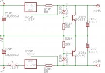
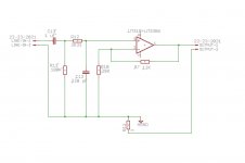
No, wrong schematic you should refer to this one:
Replace 1N5244B with 1N5242B (Mouser 1N5242B-TR).
For R101/R201 use a koa SPR1 (660-SPR1LT52R510J).
BC639 and 640 are better performing if the -16 version is selected (863-BC639-16ZL1G and 863-BC640-016G )
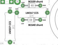
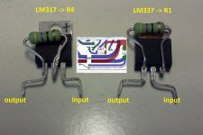
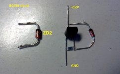
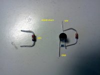
You can mount all on board, simply fit the CCSs (one reg and one resistor) in R1/R4 and transistor/zener/resistor in ZD1/ZD2.
I suggest you to start with CCSs and the actual zeners, if it works than proceed replacing zeners with shunts.
WARNING
I've did it on the fly, there may be errors, check before doing anything
Attachments
Last edited:
thanks clave! this is just what I needed so that I didn't have to be scratching my head all day.
You're welcome
")
But I think you should scratch your head a bit to check...
can i use caddock film resistors in place of koa, though?
edit: oops just checked their catalogue and it seem that caddock only comes in 50ohm.
Sure you can, 50R is perfectly fine and it's the value I'm using...
Caddocks sound better then KOAs in that position.
I've suggested KOAs only because they cost less (they sound good too).
Tell us, which resistor parameter is achieving that feat?
The only objective diffence is that KOAs are carbon film, Caddock thick-films.
To my ears they sound different, if you're not willing to try and find for youself you're free to consider me mad... not much different from usual, isn't it?
No, wrong schematic you should refer to this one:
The difference between the two schematics is just the divided and decoupled current source resistor, isn´t it?
What´s wrong with the extra decoupling?
Not that I´m an expert, but this mod is, for example, one of the "best of" mods for naim preamps naim 321 current source mod.
Is it personal preference? Apparently it also simulates better.
But again, I´m not an expert.
I think I will draw a little (30x30mm) PCB for diy-etching, that fits into the R1,R4 holes from above and incorporates the improved regulator.
I just like drawing PCBs...
The difference between the two schematics is just the divided and decoupled current source resistor, isn´t it?
It is and I think it's a bit risky (more later)
What´s wrong with the extra decoupling?
Not that I´m an expert, but this mod is, for example, one of the "best of" mods for naim preamps naim 321 current source mod.
That mod (pi-filter) is very effective on resistors present on rails for ripple and noise but R101/R201 are not properly on rails... they're in the feedback loop of the LM3x7 used as a CCS...
I wouldn't put a shunt cap in that loop, it will interfere with CCS operation.
Read what AndrewT wrote about that silly filter:
A filter inside the feedback loop.
I can't recall seeing that before.
I wonder what the filter is achieving?
Half sinewave?
Does that incorporate the spread of odd order harmonics?
I wouldn't put a shunt cap in that loop, it will interfere with CCS operation.
OK.
Not that I fully understand this, but I won´t use the shunt cap.
Here is another thing that was spinning in my mind.
I apologize in advance, if this undermines certain myref-principles like simplicity and cost and people get offended by this.
On pinkfishmedia, there is a popular poweramp-design named HackerNAP. It is a NAP135 derivative with heavily improved power supply concept.
The HackerNAP has totally separated front-end and output-stage power supplies. In a way it resembles the myref, which also has a unregulated output-power supply and a regulated front-end-supply.
The remarkable thing with the hackerNAP is however, that it also uses separate transformers and rectifying, so that the noisy GND-lines of the output don´t interfere with the not so noisy GND-lines for the front-end. This makes the hole thing quite complicated, but is also considered one of the main reasons for its amazing sound.
When I would experiment with off-board-regulation for the Myref, would it be technically possible to use a small second transformer for the shunt reg? This way, GND-lines would be separated and maybe there would be even sound improvement.
My question is: Would it be advisable? I´m sure the design of the Myref is different than a typical NAP-amp, and I´m not an electric engineer, more an interested bodger. Eventually the hole thing would for sure go unstable with different supplies and there I am with my silly idea.
Otherwise, if I already had the improved off-board shunt reg, I could as well use a second transformer with possible sonic gains....
So, what do you think?
The remarkable thing with the hackerNAP is however, that it also uses separate transformers and rectifying, so that the noisy GND-lines of the output don´t interfere with the not so noisy GND-lines for the front-end.
From what I can undertand, most part of noise injected by power section is current noise.
The Fremen Edition PS do a good job dealing with such noise.
When I would experiment with off-board-regulation for the Myref, would it be technically possible to use a small second transformer for the shunt reg? This way, GND-lines would be separated and maybe there would be even sound improvement.
IMHO it's not advisable to have separate PS grounds (signal ground is already separated).
In fact, in My_Ref, LM318 and LM3386 (along with compensation networks) can be considered as a single power opamp:
So, by istinct, to me sounds wrong to have separate trasnformers (and grounds).
Which path will take current returns?
There will be ground loop problems?
I don't know...
Maybe AndrewT, who is more technical oriented, could help us understand.
Attachments
Trying the same scheme on normal Chip amp design improves performance quite a bit. But still falls short of the MyRef type current drive. I think the future upgrades posted by Dario is going to beat lots of commercial amplifiers out there. I am still curios how good the Chip amp can go though.Those posts do not seem to refer to any setup. But I think the critical parts are increasing C4 to 1uF X cap and also using 3300uF 80V in parallel on the main DC for LM3886, and I have C12 and C13 removed. These seem to have the major impact for me. C7 changed to an X cap of same value. Snubbers close to the LM3886 improved the detail a bit.
I probably will not be going to linear power supplies, but those using these linear power supply can look into how the dynamics of power consumption currents interact with the transformer as well if single transformer per channel or two is used.
From what I can undertand, most part of noise injected by power section is current noise.
...
So, by istinct, to me sounds wrong to have separate trasnformers (and grounds).
Which path will take current returns?
There will be ground loop problems?
I don't know...
Maybe AndrewT, who is more technical oriented, could help us understand.
I think the point is to get a better 0V reference for the LM318. The reference for PWR-GND is between the two big smoothing caps (where it belongs). But since very large currents can be involved here, the reference point is exposed to bigger (current-)fluctuations (rectifier-noise, current transients, cap charge/discharge). For the LM318 supply with very small currents, it could be beneficial to set a new reference point which is seperated from the other and so gives a cleaner 0V reference. This could be achieved by either physically separate it (a second small current star ground with direct connection to the bigger large current star ground) or completley (galvanically?) isolate it from the big supply (second transformer and rectifier).
If completely seperated, I am not sure if you could let the new 0V float in reference to the old 0V, or if you should connect it also to the signal ground.
On pinkfishmedia those concepts are fare more widespread than here on diyaudio, I guess because of all the naim tweaking with its excessive PS-fetish and star grounding. Also Paul Hynes reccomends this method for, for example, the buffalo DAC - and also other DACs). Apparently the best method to power the different local regulators is a PS and transformer for each of them.
I am not sure if all amplifiers would benefit from this, everything is different and I don´t know if there are restrictions that would prevent a second PS for the LM318. But if I find the time I will try it (if nothing speaks technically against it).
why are smds used for r104/204? can substituting them for higher quality resistors bring about improvements?
if so, is that location subjected to heat? i like using cc resistors whenever i can
They dissipate quite nothing and, soundwise, they're not as critical as current setting resistors.
Any thick-film should do, with carbon films in those positions I've had mixed feeling (soundwise).
I suggested SMD format since, in a point to point retrofit space is very important and SMD permit a very compact design.
I think the point is to get a better 0V reference for the LM318.
In fact the LM318, IMHO, has not a 0V reference, it is completely floating.
For the LM318 supply with very small currents, it could be beneficial to set a new reference point which is seperated from the other and so gives a cleaner 0V reference. This could be achieved by either physically separate it (a second small current star ground with direct connection to the bigger large current star ground) or completley (galvanically?) isolate it from the big supply (second transformer and rectifier).
Probably the same goal can be achieved using a common-mode choke on LM318's PS lines but I don't think it is necessary, there are high probabilities that it disrupt the floating nature of the design.
In fact the LM318, IMHO, has not a 0V reference, it is completely floating.
But the LM318 "powersupply" on the other hand uses the 0V reference of the power-star ground. This is where this tweak would be aimed at. To improve the PS-0V reference and replace it with a new one.
You can link together as many isolated supplies as you want.
The important point is that all must have a common reference and be connected to that reference only once for each supply.
Isolated can be different transformers, or different windings on the same transformer.
The important point is that all must have a common reference and be connected to that reference only once for each supply.
Isolated can be different transformers, or different windings on the same transformer.
The important point is that all must have a common reference and be connected to that reference only once for each supply.
So I guess a good point would be the 1Ohm resistor from power-gnd to signal-gnd.
You can link together as many isolated supplies as you want.
The important point is that all must have a common reference and be connected to that reference only once for each supply.
Thanks Andrew.
So, If I've understood correctly, an LM318 dedicated supply (including trasnformer) should have its ground connected, in a sngle point, to the general amp's ground.
Then there's no reason to separate PS if we're concerned about grounds pollution... right?
probably not.So I guess a good point would be the 1Ohm resistor from power-gnd to signal-gnd.
Create your Main Audio Ground. That point is likely to NOT be coincident with a 1ohm resistor.
Hallo Andrew,
what do you mean by "main audio ground"?
I thought signal ground and power-ground are connected via an 1ohm resistor.
So to connect a further power ground, I would have chosen the power ground end of the 1ohm resistor.
To create a true connection between three grounds, the 1 ohm resistor could be omited and the necessary bridge in its place could be the main grounding point
Or do I understand something wrong?
Thanks Andrew.
So, If I've understood correctly, an LM318 dedicated supply (including trasnformer) should have its ground connected, in a sngle point, to the general amp's ground.
Then there's no reason to separate PS if we're concerned about grounds pollution... right?
Hallo Clave,
With my limited understanding, a second star-ground for the LM318 would reduce the noise on the LM318 0V-reference. A seperate transformer would push this even further, because then there are no shared 0V lines anymore, only at one point on the PCB to create a shared reference.
What do you mean with "general amp´s ground "?
I would choose a point where signal-ground, power-starground and LM318-starground meet.
- Home
- Amplifiers
- Chip Amps
- My "audiophile" LM3886 approach