Brett said:LOL. Are you serious?
Well...I was, but now in looking at prior posts a bit more carefully, I'd say there was a bit of rudeness from several posters including the author. My apologies.
...When is a problem not a problem...
Hi Joel,
Joel said:
But I had actually said:
So I did refer to amplitude... but it's not simple signal level related but rate of change of voltage level related. This means it can occur a less than full amplitude signals (but is less likely too above about 8KHz for music spectrum reasons)
Slew rate is directly related to rise time for a specific amplitude and hence always input signal and gain related. And normally (i.e.99.9%) of music signals have decreasing energy above about 8KHz...as I stated your amp will rarely suffer noticable slew rate distirtion but I would expect it's higher order distortion products to be higher than it would be with your driver running at 3mA - not a huge difference but noticeable. And it may well be that the higher level odd order distortion products match well with the even order distortion products from your 71 to give a better sounding distortion spectrum than each valve has individually hence my synergy comment...
But, as several have found, running the driver with lots of headroom i.e. up to 6dB can improve the sound even more - the sound relaxes and opens up and can get sweeter. Horrible subjective terms that seem right to those that have heard it but don't help much if you haven't. In measurement terms this relates to a removal of driver distortion products from the output spectrum leaving the output stage distortions to dominate. Now one needs a very linear output stage....
BTW Slew Rate it's not normally power supply limited in Class A but stage current drive limited - the ability of the active device to dump current into a capacitive load at a rate that doesn't impair the voltage build up across the capacitive load. This results in distortion on the higher harmonic components of the signal effectively starting to squeeze them out. NOTE the greatest voltage rate of change of the signal is about the zero point crossing -where class A amps are most linear - so it is important as a residue distortion in such systems.
Dimitri's amp. has only 20% of the necessary current drive for undistorted signal input to the 2A3 - he will not hear what the 2A3 is capable of - he will hear the effect of insufficent current drive from the driver stage. He might like that and find it an improvement on what he is used too but it could be better by apply basic engineering principles to his amp.
Joel, you are usually rationalist in your approach - why are you arguing against the good engineering approach here.? I don't understand why you have a problem with this... The amplifer should be designed competently and then tweaked to improve it's sound to the owners liking. All we have been trying to do here is advise Dimitri to design his amp better by basic engineering and encourage him to experiment. I said build it both ways and listen to each, then he can judge for himself the right and wrongs of the case. From his remarks on no current flow through a capacitor, he clearly doesn't yet understand how passive components work - we will help him if he lets us...that is part of what we are here for...We get frustrated sometimes, and that shows sometimes...but we are trying to help...
This hasn't been an SE versus PP debate where there is right on both sides. Dimitri's is a black and white case. Yours, as I said, is grey")
ciao
James
Hi Joel,
Joel said:
So, making a blanket statement like "...starts to slew limit at above 10kHz..." is rather meaningless except in the context of a specific amplitude.
But I had actually said:
Your amp starts to slew limit at above 10khz and full amplitude signals...You won't often hit it....
So I did refer to amplitude... but it's not simple signal level related but rate of change of voltage level related. This means it can occur a less than full amplitude signals (but is less likely too above about 8KHz for music spectrum reasons)
Slew rate is directly related to rise time for a specific amplitude and hence always input signal and gain related. And normally (i.e.99.9%) of music signals have decreasing energy above about 8KHz...as I stated your amp will rarely suffer noticable slew rate distirtion but I would expect it's higher order distortion products to be higher than it would be with your driver running at 3mA - not a huge difference but noticeable. And it may well be that the higher level odd order distortion products match well with the even order distortion products from your 71 to give a better sounding distortion spectrum than each valve has individually hence my synergy comment...
But, as several have found, running the driver with lots of headroom i.e. up to 6dB can improve the sound even more - the sound relaxes and opens up and can get sweeter. Horrible subjective terms that seem right to those that have heard it but don't help much if you haven't. In measurement terms this relates to a removal of driver distortion products from the output spectrum leaving the output stage distortions to dominate. Now one needs a very linear output stage....
BTW Slew Rate it's not normally power supply limited in Class A but stage current drive limited - the ability of the active device to dump current into a capacitive load at a rate that doesn't impair the voltage build up across the capacitive load. This results in distortion on the higher harmonic components of the signal effectively starting to squeeze them out. NOTE the greatest voltage rate of change of the signal is about the zero point crossing -where class A amps are most linear - so it is important as a residue distortion in such systems.
Dimitri's amp. has only 20% of the necessary current drive for undistorted signal input to the 2A3 - he will not hear what the 2A3 is capable of - he will hear the effect of insufficent current drive from the driver stage. He might like that and find it an improvement on what he is used too but it could be better by apply basic engineering principles to his amp.
Joel, you are usually rationalist in your approach - why are you arguing against the good engineering approach here.? I don't understand why you have a problem with this... The amplifer should be designed competently and then tweaked to improve it's sound to the owners liking. All we have been trying to do here is advise Dimitri to design his amp better by basic engineering and encourage him to experiment. I said build it both ways and listen to each, then he can judge for himself the right and wrongs of the case. From his remarks on no current flow through a capacitor, he clearly doesn't yet understand how passive components work - we will help him if he lets us...that is part of what we are here for...We get frustrated sometimes, and that shows sometimes...but we are trying to help...
This hasn't been an SE versus PP debate where there is right on both sides. Dimitri's is a black and white case. Yours, as I said, is grey
ciao
James
Brett,
Here are some questions regarding your original responses in this thread.
What is your thinking on this? Is there enough of a benefit to offset the fact that you need a bigger coupling (and less good sounding) cap?
I'm going to wind 2 bifilar 2.5VCT secondaries on to a small toroid from which I've stripped the secondaries. Any suggestions on where I might find material suitable for an electrostatic shield? I've only found adhesive backed copper foil at hobby shops. I'm worried the adhesive might catch fire. The good 3M stuff is impossible to find at retail here and too pricey anyway.
Here are some questions regarding your original responses in this thread.
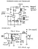
Brett said:- grid leak is a bit high in value. I'd try 1/2 to 1/4 of this and adjust C1 up accordingly. An IT or a grid choke would be <i>much</i> better.
What is your thinking on this? Is there enough of a benefit to offset the fact that you need a bigger coupling (and less good sounding) cap?
- Mains trans should have an electrostatic sheild (EI core), or be of dual bobbin constuction. A seperate ES sheilded filament trans would be nice.
I'm going to wind 2 bifilar 2.5VCT secondaries on to a small toroid from which I've stripped the secondaries. Any suggestions on where I might find material suitable for an electrostatic shield? I've only found adhesive backed copper foil at hobby shops. I'm worried the adhesive might catch fire. The good 3M stuff is impossible to find at retail here and too pricey anyway.
Jef et al
2A3 grid leak:
The RCA data says: For cathode bias, no more that 0.5M ohm.
So I would be happy with that on an RCA valve.
I wonder whether the other brands are as stable?
If it were mine, I might chose the next value down, for safety.
Coupling cap:
Could be a magnitude smaller at least. Having an excessively high value can make for unpleasant artifacts at overload.
ES shields on torroids:
I believe some ES shields are just a thick winding (or a number of), with one end only earthed.
Perhaps you should have left the original secondary on.
Cheers,
Toroids and E/S screens
Tricky. It's as well to remember that transformer manufacturers consider an E/S screen to be a safety feature that prevents arcing from primary to secondary, rather than an RF screen. Thus, as John suggests, they will quite cheerfully wind a layer of wire, connect to one end, and call that an E/S screen. As far as you or I are concerned, their screen has holes, and is connected via an inductor.
I don't see a fire risk with copper tape from a hobby shop. After all, you weren't intending to let the transformer get significantly hot were you?
A problem I do foresee is the winding of tape becoming a shorted turn. You might want to use kitchen foil to cover one side of the toroid and the circumference, then run a strip of insulating tape all the way round the circumference of the toroid, then use foil to cover the other side. Solder that works on aluminium can be readily bought, but it contaminates the tip of your iron, so keep that tip for aluminium jobs.
Re: ...When is a problem not a problem...
James, thanks for the further explanation.
And I'm certainly not 'arguing against good engineering'! I just had a few questions, I still have a few more, and I remain a bit of a skeptic for now. I hope that doesn't bother anyone.
Well, therein lies the problem. Brett especially has a very abrasive, condescending way of 'helping'. To him there is only one way of doing everything, and everyone else is ignorant. It seemed in a few posts like you had the same attitude, which is... un-fun.
Also, current doesn't flow through a capacitor. It just seems like it does!
Cheerios
James, thanks for the further explanation.
And I'm certainly not 'arguing against good engineering'! I just had a few questions, I still have a few more, and I remain a bit of a skeptic for now. I hope that doesn't bother anyone.
James D. said:From his remarks on no current flow through a capacitor, he clearly doesn't yet understand how passive components work - we will help him if he lets us...that is part of what we are here for...We get frustrated sometimes, and that shows sometimes...but we are trying to help...
Well, therein lies the problem. Brett especially has a very abrasive, condescending way of 'helping'. To him there is only one way of doing everything, and everyone else is ignorant. It seemed in a few posts like you had the same attitude, which is... un-fun.
Also, current doesn't flow through a capacitor. It just seems like it does!
Cheerios
AC/DC ONCE MORE.
Hi,
Never heard of *alternating current I suppose?
Joel,
I recall having explained this before to you.
Try to put a cap on each of toy AC fed heaters and tell me where the current goes.
Cheers,
Hi,
Also, current doesn't flow through a capacitor. It just seems like it does!
Never heard of *alternating current I suppose?
Joel,
I recall having explained this before to you.
Try to put a cap on each of toy AC fed heaters and tell me where the current goes.
Cheers,

MY GOODNESS.
Hi,
Last try:
Define *I* in Ohms' law.
According to your theory a capicitors' ability/disability to pass current is dependent on it's DA which is true to some extend.
But...if I were to make a PSU with air dielectric caps or teflon caps I would get what ?
No current any more??
What's the purpose of a coupling cap in your opinion?
Cheers,
A capacitor can be charged by applying a potential difference (PD) across the plates. The applied PD causes charges to buildup on one plate and be depleted from the other in a 1:1 ratio. Although current does not actually flow through the capacitor, current flows in the circuit. So, in effect, there is a pseudo-current flowing 'through' the capacitor.
Due to the charge buildup on the plates, a potential difference develops across the capacitor which opposes the applied PD. Once this PD equals the applied PD, the current stops flowing in the circuit.
http://www.jcphysics.com/toolbox_indiv.php?sub_id=19
and here's another one:
http://www.radioelectronicschool.com/reading/reading13.pdf
If you'd like more links, or suggested reading, please let me know!
Cheers
...mea culpa...
Hi Joel,
Looking back at my posts, some of them were more abrasive than they should have been. Sorry... one of my many failings is to get too 'involved' in a discussion and over state my position to the detriment of others... My wife says I'm better than I've ever been at controlling this but I still have a long way to go!!! So your in very good company
Your point about capacitors and ac current flow is very well made. No current (or very very little) flows across the dielectric just charge movement onto and off the plates. Of course energy transfer takes place via the electric field between the plates and this drives the charge movement out of the capaciter with the charge movement into the capacitor driving the establiahment of this field. It is the driver stages ability to power this charge movement into the capacitance associated with the output stages grid circuit that we are considering here...
I would be pleased to try to answer your questions, I like your common sense approach to electronics and questioning of accepted wisdom. I can't promise not to get over emotional but if I do just call me on it and I'll apologise again... Your questions either further my understanding by driving it deeper (I'm coming back to valves after a long layoff...) or take it into new areas of applicability - so many thanks!
ciao James
Hi Joel,
Looking back at my posts, some of them were more abrasive than they should have been. Sorry... one of my many failings is to get too 'involved' in a discussion and over state my position to the detriment of others... My wife says I'm better than I've ever been at controlling this but I still have a long way to go!!! So your in very good company
Your point about capacitors and ac current flow is very well made. No current (or very very little) flows across the dielectric just charge movement onto and off the plates. Of course energy transfer takes place via the electric field between the plates and this drives the charge movement out of the capaciter with the charge movement into the capacitor driving the establiahment of this field. It is the driver stages ability to power this charge movement into the capacitance associated with the output stages grid circuit that we are considering here...
I would be pleased to try to answer your questions, I like your common sense approach to electronics and questioning of accepted wisdom. I can't promise not to get over emotional but if I do just call me on it and I'll apologise again...
Your questions either further my understanding by driving it deeper (I'm coming back to valves after a long layoff...) or take it into new areas of applicability - so many thanks!ciao James
James, I'm having trouble finding reference to slew rate other than being device dependant. In other words, active devices (opamps, etc) with a quoted V/mS. I've never seen that value given in data sheets for any tubes. Am I looking in the wrong place?
I would assume that the device's slew rate would be the starting point for any further calculations.
I would assume that the device's slew rate would be the starting point for any further calculations.
Thanks Frank, but since I've already defined the term twice, and posted the same formula you just did, I obviously don't need an explanation.
Let me put it a different way: where do I find the calculated slew rates for various tubes? Because isn't this critical to the formula I=C*Sr?
Let me put it a different way: where do I find the calculated slew rates for various tubes? Because isn't this critical to the formula I=C*Sr?
Slew Rate specs.
Joel,
I too have only seen it explicitly quoted for amplifers or equivalent devices. That is because it is associated with the performance of a particular device in a given circuit - so it is a property of an active device or devices deployed in a given circuit - not an intrinsic property of the device itself... In other words, each active device has a maximum amount of current that it can deliver, but the rate at which, and how much it can pump of this current is circuit dependent...
In the same way it isn't possible to quote the slew rate needed to cleanly drive a given valve because it depends on how the valve is deployed in a circuit. For any given circuit the slew rate requirement can be calculated. One of the easiest ways of doing this is using the formulas spreadsheet on the VT52 web site. It is a good quick way of getting values for lots of different parameters.
Jim de Kort formulas spreadsheet
This gives the current required to drive a given valve - at audio frequencies we assume that we are not frequency response limited in our active device and therefore if the current is available then it can be delivered at the required rate...
ciao
James
Hmmm.. well, I actually have seen specific transistors with quoted slew rates, and it was not mentioned in the context of a circuit.
Anyway, just playing around with some numbers I seem to get wildly different values than you did.
Taking my 71-A amp:
at 20kHz, with an input swing of 80V pk-pk, I get a required slew rate of 10.05V/mS
So, using I=C*Sr, with an input capacitance of approximately 8pF shall we say, I get a current requirement of .00008mA
??

- Status
- This old topic is closed. If you want to reopen this topic, contact a moderator using the "Report Post" button.
- Home
- Amplifiers
- Tubes / Valves
- My 6SL7, 2A3 SE design