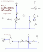
ok this is the final version of my 6SL7, 2A3/6A3/6B4G Single Ended design. feel free to critique. also was wondering if this will drive 91dB speakers to sufficient volume. and seeing as to what happened to my last post, if we could stick to the matter at hand... thx.
Attachments
Well, nobody had replied...so...
Dmitri,
"Keeping to the matter at hand": I don't know.
What is your anticipated output power?
Also, have you considered what the unbypassed cathode resistor is doing to the anode resistance of the 2A3, and it's already low value of anode load (the transformer).
My thoughts,
Cheers,")
Dmitri,
"Keeping to the matter at hand": I don't know.
What is your anticipated output power?
Also, have you considered what the unbypassed cathode resistor is doing to the anode resistance of the 2A3, and it's already low value of anode load (the transformer).
My thoughts,
Cheers,
Hi Dmitry,
First things first.
<b>wondering if this will drive 91dB speakers to sufficient volume</b>
No. About 10dB more sensitivity in the speakers, or 10dB more amp power would be my <i>minimum</i>
<b>feel free to critique.</b>
OK, but unless you listen at low volume to simple bass light music, the amp won't produce enough power, and will sound disappointingly wimpy.
Output stage.
- biassed incorrectly. An Rk of about 750 ohms will give approx 60mA and Vg = -44V, right smack bang in the middle of the 2A3 sweet spot.
- bypass the cathode resistor with about 100uF of quality capacitor.
- 330V for the output stage is a bit high. In line with my bias recommendation above, reduce it to 295 - 300V
- grid leak is a bit high in value. I'd try 1/2 to 1/4 of this and adjust C1 up accordingly. An IT or a grid choke would be <i>much</i> better.
Driver
- Why 6SL7? It will have a gain if about 70 in this application (so amp sensitivity of 600mV) which is a bit high for modern systems, and may present some noise issues, especially with an active preamp. With a pre, you'll also be throwing away tons of gain.
The output Z of the driver will be about 60K. Yuk!. It'll sound like an old fashioned clock radio. A 6SN7, 6H30, ECC99, C3m (trioded) or even one of the 6C45/417/5842 would be better, with the ECC99 being my first choice (ECC99 ; B+ = 300V, Va = 100V, Ia = 20mA, Rk ~300ohm probably bypassed, Ra = 10k, at a guess)
DHTs sound a lot better driven by a tube with some grunt, or all you hear are the driver colourations very clearly. I know there are some people here who will disagree with this, but this is my own direct experience, as well as people like Paul Joppa.
- unless the pot at the input is there as your only volume control, get rid of it.
PSU
- First C is OK, choke should be about 10H, second C about 100uF. If you drop the output stage voltage to 300V as suggested, you can probably run the driver off the same supply. Note, I haven't run the numbers on the simulator yet, but that should be close. Of course another LC stage wouldn't hurt.
- Add some common mode chokes to the filament supplies for the 2A3's, as well as some smallish caps right across the socket pins, to remove any HF noise that comes through from the mains trans. The filament on a DHT is as sensitive to noise as the grid.
- Mains trans should have an electrostatic sheild (EI core), or be of dual bobbin constuction. A seperate ES sheilded filament trans would be nice.
HTH
...Listen to Brett-san...
Hi Dimitry,
Please listen to Brett's comments on your design. He is giving very, very good advice. The same advice was in your last post before the thread discussion widened.
I recommend you build the design your way and see how it sounds and then revamp it along the lines Brett suggests and listen to that. See if you think we are giving good advice.
Your power supply design is not going to remove enough mains ripple to prevent hum on the output. According to psu11 sim. you have over 700mV of ripple for the 2A3 and 235mV of ripple for the 6SL7 - as this is running at a gain of 70 you will have lots of hum on your output. If you do not have access to bigger chokes and capacitors then I recommend a regulated power supply of any type...You should be aiming for less than 5mV ripple for the 2A3 and at least an order of magnitude less for the 6SL7 - IMO.
ciao
James
forgot to mention that the 6SL7 is biased at -1.5V and the 2A3 at -40V. also the 6SL7 is setup to produce a gain of around 47 as far as i can remember from my calculations, not the maximum 70. also, for the lack of cathode bypass capacitors is to minimize distortion. and to answer dhaen in what my anticipated output is, well somewhere near a 12AX7 sections in series with EL84 output amp runnin near 2-3watts. also, Brett i dont see how u can suggest a 6SN7 instead of a 6SL7, seeing as how the 6SN7 has a max gain of only 20. ive seen a few amp designs using a 6SN7 put in series then driving a 2A3, so that would b about the same as using a single 6SL7, unless there is some current difference between the two. please reply.
Hi Dmitri,
I think your LF distortion may be worse with no cathode bypass, of course this depends on the inductance of your transformer, but probably.
By leaving the cathode unbypassed, you are providing some local NFB, but the Ra of the 2A3 is then higher, and so it has to work harder to get any current into the output transformer.
Also, the parasitic capacitance of the transformer will become more significant, so HF may drop slightly.
That's how I see it.
Cheers,
2A3
Hi,
Audibly and measurably so.
Setting a side PSU filtering and input stage,this what I would do:
B+ 310 VDC will give you about 300 VDC on the 2A3 anode.
R6 lower to 750 R + add Ck 100 mF 160 VDC.
R5 lower to 220K.
And with a bit more work you loose C1 too and go Loftin White style.
Cheers,
Hi,
Also, the parasitic capacitance of the transformer will become more significant, so HF may drop slightly.
Audibly and measurably so.
Setting a side PSU filtering and input stage,this what I would do:
B+ 310 VDC will give you about 300 VDC on the 2A3 anode.
R6 lower to 750 R + add Ck 100 mF 160 VDC.
R5 lower to 220K.
And with a bit more work you loose C1 too and go Loftin White style.
Cheers,
I ran your numbers in Livecurves, and I get Vg = -59V, Ia = 48mA, with a loadline that dips well down into the highly pinched section of the curves. I estimate about 2.7W (2A3 cathode bypassed), with a heap of distortion, even by SET standards.mig-ru said:forgot to mention that the 6SL7 is biased at -1.5V and the 2A3 at -40V.
I don't have a very good set of 6SL7 curves in front of me, so I'll take your word for it. However with such a high Ra, and a low B+, the current through it will be very low, raising the Rp even higher than I calculated. Again, you'll be running it down into the highly non linear parts of the plate curves. Therefore even more gutless than I thought, and whilst possible suitable for a guitar amp gain stage, it will sound like crap as a driver.also the 6SL7 is setup to produce a gain of around 47 as far as i can remember from my calculations, not the maximum 70.
Lack of cathode bypasses in both these stages will increase distortion for the reasons outlined previously in this post, and the one before. It will also produce almost no power, as the output impedance of the 2A3 stage wil be greater than the load.also, for the lack of cathode bypass capacitors is to minimize distortion. and to answer dhaen in what my anticipated output is, well somewhere near a 12AX7 sections in series with EL84 output amp runnin near 2-3watts.
An EL84 is not going to give 3W SE; 1.7W is greater than 8% HD in triode, let alone what it would have in pentode or UL
Interesting that you choose to pick the 6SN7 out of the list I mentioned. Whilst I generally like the 6SN7, I don't think it makes a good DHT driver. ANY of the others would be far better. Even with less gain it (6SN7) would still be a better choice, because, bypassed a 6SN7 will actually drive it decently (not really well). What is the point of having a linear tube (2A3) and then putting an athsmatic driver in front of it to colour it all to hell? And this with inefficient speakers.also, Brett i dont see how u can suggest a 6SN7 instead of a 6SL7, seeing as how the 6SN7 has a max gain of only 20. ive seen a few amp designs using a 6SN7 put in series then driving a 2A3, so that would b about the same as using a single 6SL7, unless there is some current difference between the two. please reply.
BTW, two cascaded 6SN7 sections would give more gain than a single 6SL7.
hmm wow, maybe instead of running computer programmes you should pick up a some data sheets for the tubes and draw some load lines, seemed to work for engineers for decades before computers came about. anyway, the 6SL7 2nd harmonic distortion calculates near 0%, some rounding error yes, but still close. and 1.5 bias with a 120k resistor gives me a pretty linear swing. as for how you figured the 2A3 at -59 i dont know either, i did it by drawing load lines, checked the design with some tubeheads i know, and they said it was fine.
Dmitry,
I agree with Frank, go ahead and build it.
I think all you wanted us to do was rubber stamp your design, and now you're annoyed because I found a number of GLARING faults in it. I really doubt you had anyone with any real knowledge look at it, else they would have found the same faults. We're not talking arcane esoterica here, but basic principles, and you got them wrong, showing no understanding for the subject at all.
<b>hmm wow, maybe instead of running computer programmes you should pick up a some data sheets for the tubes and draw some load lines, seemed to work for engineers for decades before computers came about.</b>
Like der, and the saddest of cheap shots. Live curves was written by Tom Broskie of Tubecad. When you know more on the subject than him, please enlighten us. I told you I don't have a set of good curves for the 6SL7 (meant bad scan), but I've been doing this for decades, so I eyed them in.
Since you know so much about the subject, draw the loadlines, and scan and post them here, along with <i>all</i> the operating parameters for the stages with the reasoning behind the choices you made, and the the maths for for peer review. Go on, what do you have to hide? Undoubtedly you'll be doing us all a favour, and we'll be forever indebted to you for sharing your vast knowledge and understanding.
Then build it, exactly to your schematic, and we'll get it measured by someone in the US, and publish the results here.
Hi mig-ru;
Re: your query about speaker efficiency and a 2A3, FWIW, as I type this post I'm running a DIY 2A3 into 95 dB efficient DIY fullrange speakers and it's fine for both volume and dynamic range. I've also run that 2A3 into 89dB SPL speakers (ancient EPI 100's with mods) and it was fine in a smallish room (about 11' by 11' with 8' ceiling) for most listening. Orchestral music was somewhat limited though.
However, that's not the whole story. I also ran a pair of Infinity IL 10's with the same 2A3 and it was most unsatisfying in the same listening room (although those same speakers are of the same efficiency as the EPI's and they sound great with my 40 watt PP EL34 amp). IMHO the crossover (more importantly the LACK of a crossover) in your speakers is as important with flea powered amps as is the rated efficiency of the speakers.
So, if your '91dB SPL' speakers have a complex crossover, with notch filters et al, they may sound lifeless and lacklustre with the kind of power output you can expect from a 2A3. However, if the crossover is a single cap in series with the tweet, that's a different matter entirely IME.
Just my 2 cents worth.
Good luck on your amp!
I have found the best operating point for the 6SL7 used as a driver is a plate current of 1.6mA, a plate resistor of 100K, a bias around -1.05 volts, and a B+ of 340V.
This delivers its musical best.
But it does not have a lot of drive; you'd better be careful that 2A3 never slips into grid positive.
I trust this is helpful.
Cheers,
Hugh
www.aksaonline.com
This delivers its musical best.
But it does not have a lot of drive; you'd better be careful that 2A3 never slips into grid positive.
I trust this is helpful.
Cheers,
Hugh
www.aksaonline.com
brett sorry if i sounded argumentive but im not saying ur are wrong, i just dont see how u come to ur conclusions. first of all for the driver wouldnt u need as much gain as possible? due to only AC voltage passing through the coupling cap onto the next stage. and why does the driver need more current? i thought that keeping the grid negative in respect to the cathode was so that ther was no current flow through it? as for load lines, i drew them checked, redrew, had others check and make sure they are right; could it be possible that u entered the values wrong into livecurves or possibly a glitch? ill try and get the programme and double check myself. as for the learning material i used, it is written by Norman H. Crowhurst, i hear he is pretty good at this too.
A lot of this is subjective. I'm uncertain how absolute statements like the ones made in this thread can be made.
First, the 2A3 could be enough power for you. I'm happy with a 45 that produces around 1 Watt at maximum output for 99% of the material I listen to and my speakers are less sensitive than yours. You just have to try it and see.
While I don't agree with all of the design choices you've made, certainly it's a bit far out to call some of them faults. IMO, it's very easy for a high current driver stage to make an amp sound awful. It's definitely not plug and play. That's not to say that a well implemented one wont sound very good, but I haven't had luck with the few I've tried.
My suggestion is to go ahead and build it the way you see it and then try a few of the suggestions here. That way you'll know what you like rather than taking someone else's word for it.
No most of it is very basic engineering.jeff mai said:A lot of this is subjective.
Dmitry,
Don't let them scare you off! This is a fairly typical argument - old school vs. what they consider to be the new school of thought.
There is a good bit of truth in both camps, but the question is one of relativity, and application, no? In other words, Brett can be 100% correct about a particular issue, but no one except a bat could hear the "benefits" of it.
Anyway, there are plenty of designs, very well received in fact, that use high mu driver stages, with very low current. See the Angela instruments "model 91" for example. And I built an SE amp using a 6F5 driving a 71A. That tube only has a plate current of .9 mA! Brett, Frank, John and others would call this a design fault, and say it will definitely sound awful. Of course it doesn't. It's transparent, dynamic, and full.
So, don't be discouraged in your 6SL7 pursuits, BUT also realize that you are not going to convince them.
Don't let them scare you off!
This is a fairly typical argument - old school vs. what they consider to be the new school of thought.There is a good bit of truth in both camps, but the question is one of relativity, and application, no? In other words, Brett can be 100% correct about a particular issue, but no one except a bat could hear the "benefits" of it.
Anyway, there are plenty of designs, very well received in fact, that use high mu driver stages, with very low current. See the Angela instruments "model 91" for example. And I built an SE amp using a 6F5 driving a 71A. That tube only has a plate current of .9 mA! Brett, Frank, John and others would call this a design fault, and say it will definitely sound awful. Of course it doesn't. It's transparent, dynamic, and full.
So, don't be discouraged in your 6SL7 pursuits, BUT also realize that you are not going to convince them.
Engineering vs subjectivism
Dmitri, you have had strong opinions from both camps.
For every subjectivist amplifier that breaks the engineering rules and gets away with it, nine don't. A circuit that looks good on paper has half a chance of sounding good, but even then, it can turn out to be a lemon.
I'm afraid your circuit doesn't look very good on paper.
Attempting to drive the Miller capacitance of a 2A3 from the high output resistance of a 6SL7 with cathode feedback is asking for a rolled-off top end.
Single-ended output stages ask a lot of their output transformers, and leaving the cathode unbypassed makes life even more difficult.
Still, if you've got the bits, knock it up. It shouldn't take long to make a scruffy version. However, if you need to buy the bits, you need a much better design to justify risking your money.
- Status
- This old topic is closed. If you want to reopen this topic, contact a moderator using the "Report Post" button.
- Home
- Amplifiers
- Tubes / Valves
- My 6SL7, 2A3 SE design