lol.. Didn`t come out the way I meant it...
PCB`s went straight to *****. They had very poor quality...nuff said.
My computer crashed afterwards (got a really annoying message in XP startup, claiming system32 directory was lost or something.
Anyway, all my design and so on where lost. I`ve formatted and installed a new system, and I`ve redrawn all circuits, and a new pcb layoutprogram installed (ultiboard 2001). The PCB layouts are soon finished.
Also, the 50W project suddenly went 180W! Yey...new job=more money=bigger amp!
Hi Tahn, sorry for my late reply!
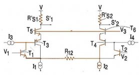
I don`t think q5/q6 need any CC`s, however, I`m a bit sceptic about stability due to the lack of CC between the collector on U9 an base on Q3. Things have been going slow lately, and I still haven`t buildt the amp. . But I`m still simulating and modifying the circuit.
I also tried swapping the diff bjt`s with jfet`s (out of curiousity of course), and the simulator showed very good numbers, not better than bjt`s...but better than I thought.
Regarding the lavardin schematic: I don`t know anything about the distortion preformance...I haven`t done any simulations...yet.
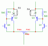
Regarding Aiace's circuit: I don`t see any reason why you should implement R3 and R4, I`ve tried values ranging from 100ohms up to 2kohm`s and the distortion increased with increasing values. No resistors at all showed best preformance.....
I don`t think q5/q6 need any CC`s, however, I`m a bit sceptic about stability due to the lack of CC between the collector on U9 an base on Q3. Things have been going slow lately, and I still haven`t buildt the amp.
. But I`m still simulating and modifying the circuit.I also tried swapping the diff bjt`s with jfet`s (out of curiousity of course), and the simulator showed very good numbers, not better than bjt`s...but better than I thought.
Regarding the lavardin schematic: I don`t know anything about the distortion preformance...I haven`t done any simulations...yet.
Regarding Aiace's circuit: I don`t see any reason why you should implement R3 and R4, I`ve tried values ranging from 100ohms up to 2kohm`s and the distortion increased with increasing values. No resistors at all showed best preformance.....
thanh said:Panzerlord!What simulate sofware are you using?I have used ORCAD But I don't know how distortion is calculated
you can do FFT and manually add it up, or you can find it under either "measurement" or "performance analysis". Just need to select a signal and apply the right measurement / analysis.
OrCad offers a video on how some of the functions work. pretty neat.
thanh said:So how is voltage gain of JFET if i use 2SK30?
You have to evaluate the diagram in its datasheet for this. Or look into its SPICE model parameter. I have neither of this for 2SK30.
But anyway, if you evaluate the formula just with typical values, you will see that the result is just 'very large'. So the total impedance of the node the current source is connected to, will be dominated by the other connections. For all practical purposes, the circuit drawn is a ideal current source.
Example BJT=BC337-40 JFET=J112 R=180 I=5mA
Simulated impedance is about 90 Meg
thanh said:Is JFET noised by electric field?Can you understand me?
No, I don't understand the question.
Regards,
Peter Jacobi
Stevens current source has greater output resistance, but the jfet introduces more noise.
The simulator showed no significant improvement in distortion preformance (probably due to the greater VA and output stage distortion). I suppose the distortion figures in the diff-stage are somewhat better (marginally).
The simulator showed no significant improvement in distortion preformance (probably due to the greater VA and output stage distortion). I suppose the distortion figures in the diff-stage are somewhat better (marginally).
PanzerLord said:Stevens current source has greater output resistance, but the jfet introduces more noise.
The simulator showed no significant improvement in distortion preformance (probably due to the greater VA and output stage distortion). I suppose the distortion figures in the diff-stage are somewhat better (marginally).
I don't think the JFET will add noise in the case of a BJT current source with JFET cascode. Gate current is close to zero, so drain current is equal to source current, which is equal to BJT collector current. Ergo: the JFET does not add noise. All the noise comes from the BJT, its emitter resistor and what is in front of the BJT.
Steven

I think jfet doesn't introduces more noise.Its noise come from electric field strengthjfet introduces more noise
- Status
- This old topic is closed. If you want to reopen this topic, contact a moderator using the "Report Post" button.
- Home
- Amplifiers
- Solid State
- My 50W class A design!