ooh, thankies.kstagger said:similar PCB is available on E-Scam
http://cgi.ebay.com/MULTI-PURPOSE-T...eZWD1VQQtrksidZp1638.m118.l1247QQcmdZViewItem
Any ideas about the gold turrets too?

CCS means constant current source. IXYS is a manufacturer of solid state devices.
Bypassing the cathode degeneration resistor means you are putting an electrolytic capacitor in the signal path--it's just as much in the signal path as a DC blocking capacitor on the output would be.
Whatever criticisms can be made about global negative feedback, one cannot possibly argue that the very local one provided by an unbypassed cathode degeneration resistor can have negative sonic contribution, let alone one worse than the insertion of an electrolytic.
You should try an unbypassed resistor. If there's not sufficient gain, you can decrease its value; there are other means for adjusting the DC operating point. You might like the sound of the capacitor better, but you might not and end up preferring the linearized tube and lack of coloration from dielectric absorption and electrolytic nonlinearities.
abzug said:You should try an unbypassed resistor.
Thanks for the suggestion
I will give it a try, and there are LED and battery bias for me to try as well. That should keep me busy 
alexw88 said:Thanks
BTW, the THD% in my measurement shown above is 0.035%.
I think that you have to measure the THD with a real THD analyzer or a spectrum analyzer -- there is something peculiar with the "shelved" noise level in your card.
Prototype Boards
For those interested, there are a couple of other prototype boards around.
This I saw on Ebay:-
http://cgi.ebay.co.uk/VERO-BLANK-PR...4196279QQihZ002QQcategoryZ50423QQcmdZViewItem
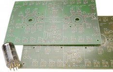
But I went for the one from ( Classic Valve Design ) pictured below.:-
www.classicvalve.ca
This features spaces for anode and cathode CCS.
Andy
For those interested, there are a couple of other prototype boards around.
This I saw on Ebay:-
http://cgi.ebay.co.uk/VERO-BLANK-PR...4196279QQihZ002QQcategoryZ50423QQcmdZViewItem
But I went for the one from ( Classic Valve Design ) pictured below.:-
www.classicvalve.ca
This features spaces for anode and cathode CCS.
Andy
Attachments
Had to change the last pic since I had the BW set at 80kHz -- this is a plot of THD% from 20Hz to 100kHz -- but this isn't the entire story:
An externally hosted image should be here but it was not working when we last tested it.
jackinnj said:Had to change the last pic since I had the BW set at 80kHz -- this is a plot of THD% from 20Hz to 100kHz -- but this isn't the entire story:
It is expected that the 2nd harmonic (and THD) will go down without the bypass capacitor, but did you noticed that 3rd harmonic went up? (as suggested by http://www.tubecad.com/2005/March/blog0039.htm )
MQracing said:
If it sounds half as good as your construction quality--- you'd have a real ear-pleaser!!!
MSL
Did I mentioned it sounds good? I really like how it sounds
Alex, in your design criteria, you mentioned second harmonic distortion. I didn't understand what you wrote; did you mean that you deliberately wanted to have some second harmonic or did you mean that you wanted it as low as possible, but with whatever is there dominated by second harmonic?
SY, I actually want some 2nd harmonic distortion because I want some "sweet" sounds.
I have done a Opamp balanced preamp which gives 0.0007% THD, with 2nd harmonics at 132dB below the fundamental. It sounds very accurate but at the same time it sounds too plain. That's why I want to try tube for its sweetness.
May be I am totally wrong about the relation between sweetness and harmonics distortion.... please share your view
Well, there was a much cheaper way to find out than build a tube amp--take your low distortion preamp and add some 2nd harmonic by software to a music file you rip to your computer...
If an amplifier is completely transparent, any euphonic distortion can be added by signal processing, which costs nothing.
If the amplifier is not transparent, then the type of distortion one can produce from it is limited by its inherent distortion, since it's very hard to fully characterize that distortion so that it can be canceled by predistortion in the signal processing.
Here's Alex's preamp with equal 1 volt output -- the lower series is with the 680R bypassed with 470uF -- the response on the analyzer is set to its initial condition of 10Hz to 500kHz
An externally hosted image should be here but it was not working when we last tested it.
jackinnj said:Here's Alex's preamp with equal 1 volt output -- the lower series is with the 680R bypassed with 470uF -- the response on the analyzer is set to its initial condition of 10Hz to 500kHz
How come you are getting 0.4% THD? That's 10x higher than mine. Can you post a FFT frequency spectrum showing the distortion content?
alexw88 said:
How come you are getting 0.4% THD? That's 10x higher than mine. Can you post a FFT frequency spectrum showing the distortion content?
Because I am running the program flat out -- the THD% in an absolute sense is less important than the comparison between the bypassed and unbypassed RK -- done under identical conditions. If I engage the 400 Hz filter to get rid of the bumpies which arise due to the non-shielded nature of the filament leads, and the halogen which illuminates my workspace, etc.., etc. I will get a lower number. All I wanted to do was illustrate the THD% at identical output levels.
- Status
- This old topic is closed. If you want to reopen this topic, contact a moderator using the "Report Post" button.
- Home
- Amplifiers
- Tubes / Valves
- My 12AX7 zero negative feedback preamp, with measurement